ASSEMBLY TIME: 30-40 minutes
Tools needed: Phillips screwdriver
TROUBLESHOOTING AIR HOCKEY FORUM GITHUB
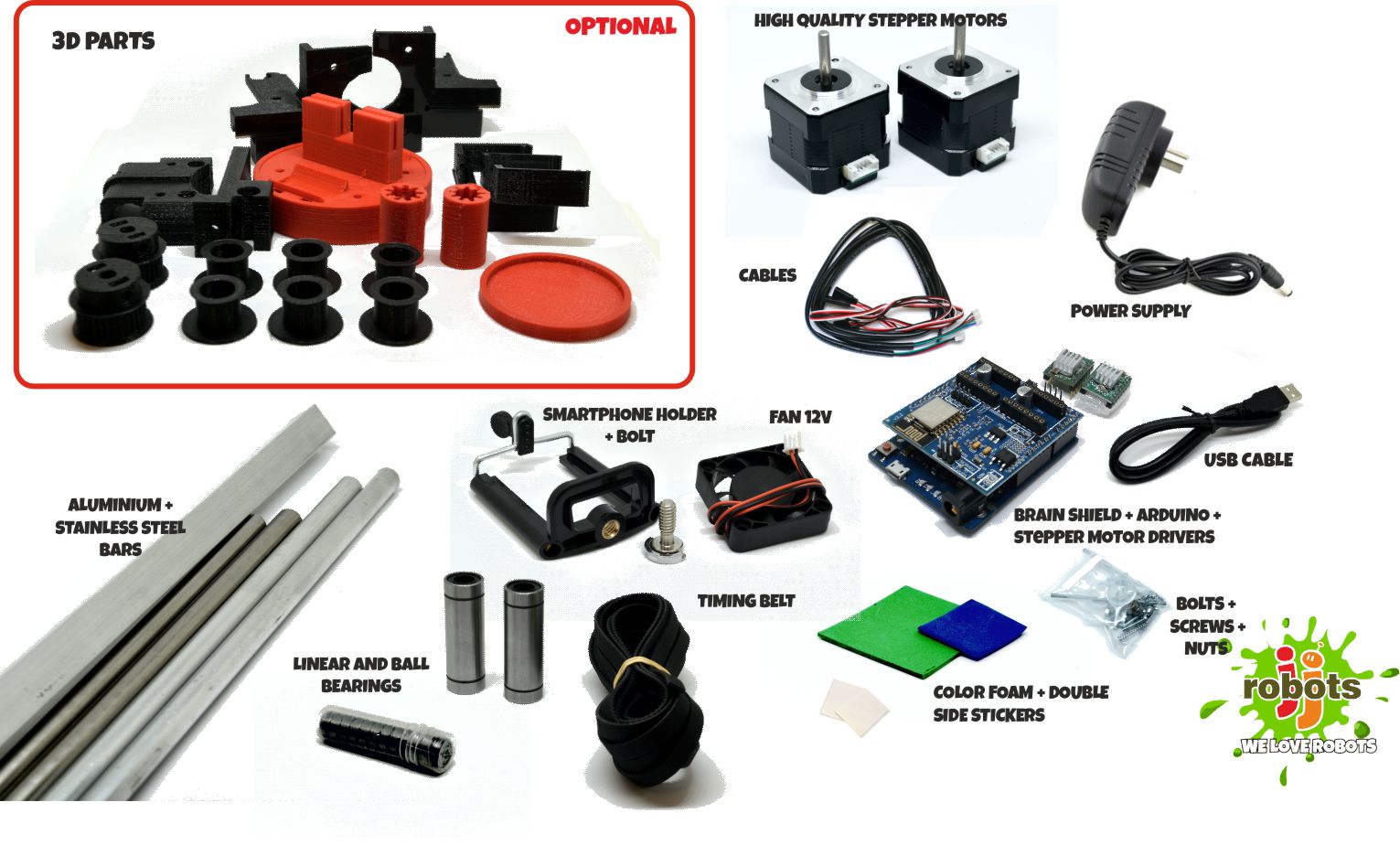
BILL OF MATERIALS:
- 12x M3 bolt 6mm
- 4x M3 bolt 10mm
- 6x M3 bolt 15mm
- 7x M3 bolt 25 mm
- 20x M3 nuts
- 2x M3 self blocking nut
- 12x M2.5 Wood screw 20 mm
- EVA FOAM (two different colours)
- 4cm 12V FAN
- 2x Stepper motor NEMA17 + cables (70+70 cms)
- jjRobots Brain Shield
- Arduino Leonardo
- 2x Stepper motor drivers A4988 + heatsinks
- 12V 2A power supply 5.5mm 2.5mm jack
- 2x LM88UU linear ball bearing
- 12x 623 ball bearings
- 2x Stainless steel bar 8⌀ 455mm long
- 2x Anodised aluminium tube 8⌀ 43.5 mm long
- 1x Aluminium square pipe 12×12 mm 71cm
- GT2 timing belt (300 cm)
- 5x zip ties (150mm x 3 mm)
- double side sticky foam
- 3D printed parts
- Air hockey table
- Android Smartphone (Lollipop OS or higher)
LINKS
SHORT INTRODUCTION:
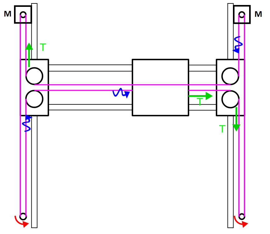
If you got the AIR HOCKEY ROBOT KIT you already have everything you need to create the robot. This will take no more than 30-40. The key for assembling a flawless working robot is the H-bot system: this structure allows the robot to move itself to any location on its playing field only using two motors. Can be detached easily so you can use the Air Hockey robot as a Air hockey table whenever you want.
You need this H-bot to run smooth and be strong at the same time. The better you set it up, the higher the accelerations you can reach with your robot. Pay attention to the tips provided throughout this guide.
The other thing to be aware of: vision system. The smartphone camera is capable of capturing up to 30 frames per second. Doing that, the robot can calculate precisely the position (and in consequence, its trajectory ) of both the robot and the puck.
This guide is fulfilled with tips, videos (they help a lot) and comments about how this robot works. The COMMUNITY will help you (and others) to find solutions to the issues that always arise.
AIR HOCKEY ROBOT: HOW DOES IT WORK? (SHORT VERSION)
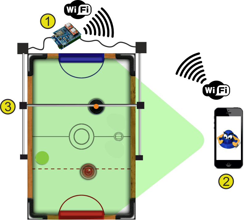
Mounted on the Air hockey table (3), this robot is always connected to your smartphone, in charge of see what is going on the playing court and make decisions.
How it works: The smartphone´s camera (2) is looking at the playing court . The camera´s captured data is processed in real time by the smartphone. Detecting the position of the puck and the “Pusher robot” (and according to the current location of all the elements on the court), your smartphone makes decisions and tells the Robot what to do via WIFI (1).
The Robot is locally controlled by the jjRobots Brain Shield (1) which dictates the speed and acceleration of the robot, sending the appropriate pulses to the stepper motors. Easy!
VISION SYSTEM: The coordinates of the puck and its trajectory are calculated using the visual data coming from the smartphone´s camera (2). Two consecutive frames are required in order to calculate the trajectory of the puck. The Air hockey robot uses its current location, the puck position and the trajectory prediction to determine its strategy – either defence, defence and attack, or a new attack. An uniform illumination is extremely important for the vision system. Avoid shadows, reflections (and if you can, fluorescent lighting).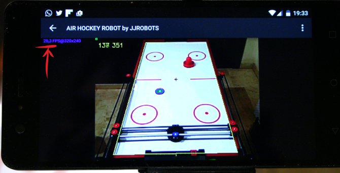
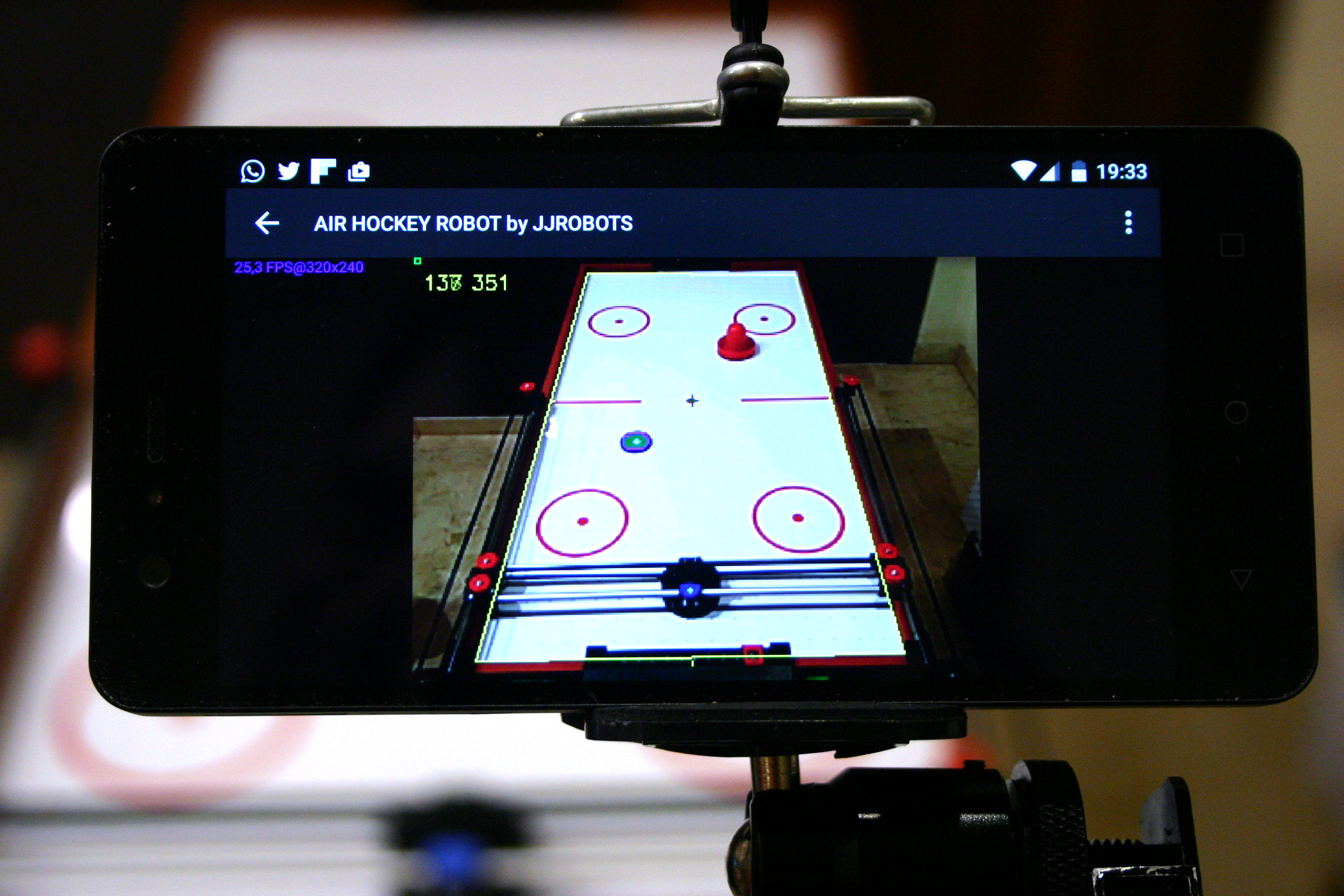
Image above: Can you see the number pointed with the red arrow? That number means the FRAMES PER SECOND (FPS). The better the lighting -> higher FPS value -> better robot behaviour

The Air Hockey robot uses two powerful stepper motors. Keep an eye on where you place your fingers!.
Sudden accelerations of the robot within its playing area could catch you unaware. Before adjusting anything remember to disconnect its power supply.
ASSEMBLING THE H-BOT (STRUCTURE)
1) Motors + pulleys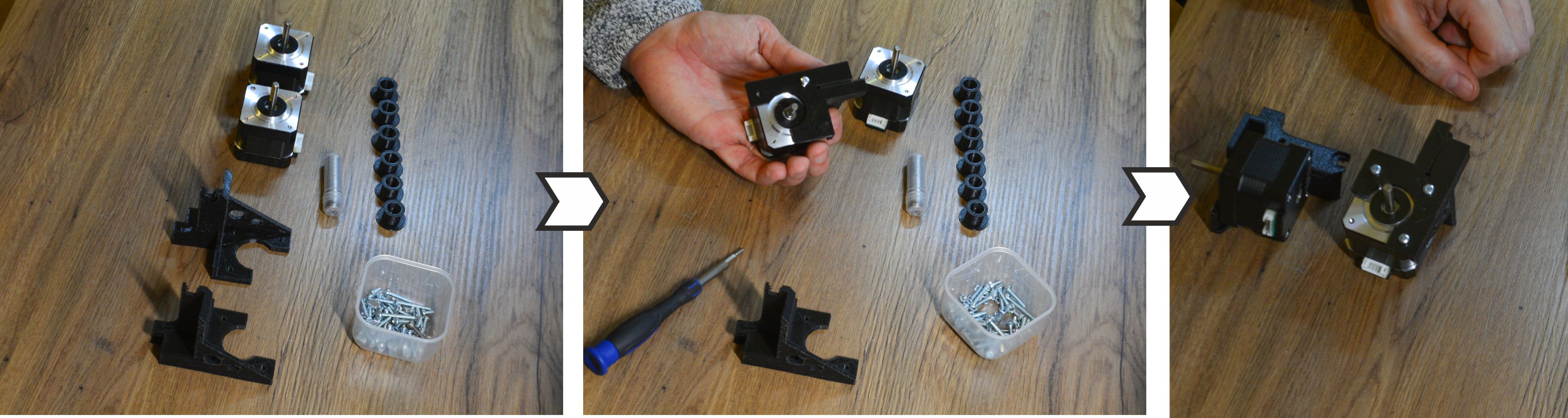
Above: Use 6x 6mm M3 bolts (3 per motor) to fix the motor to the motor supports
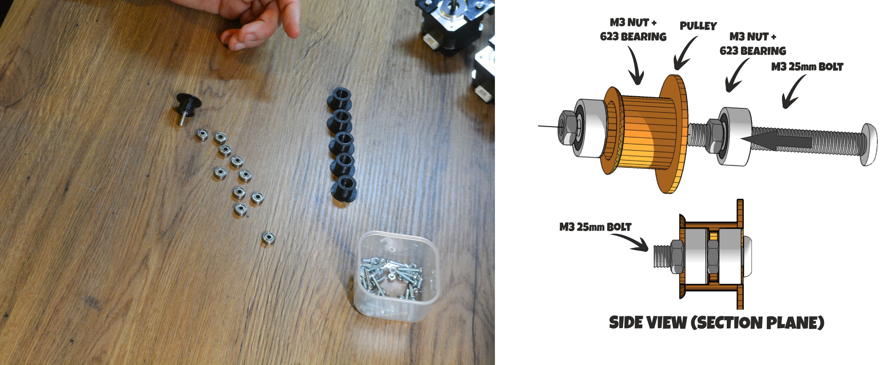
Place the 623 ball bearings (12 units, 2 per pulley) inside the plastic pulleys as indicated above.
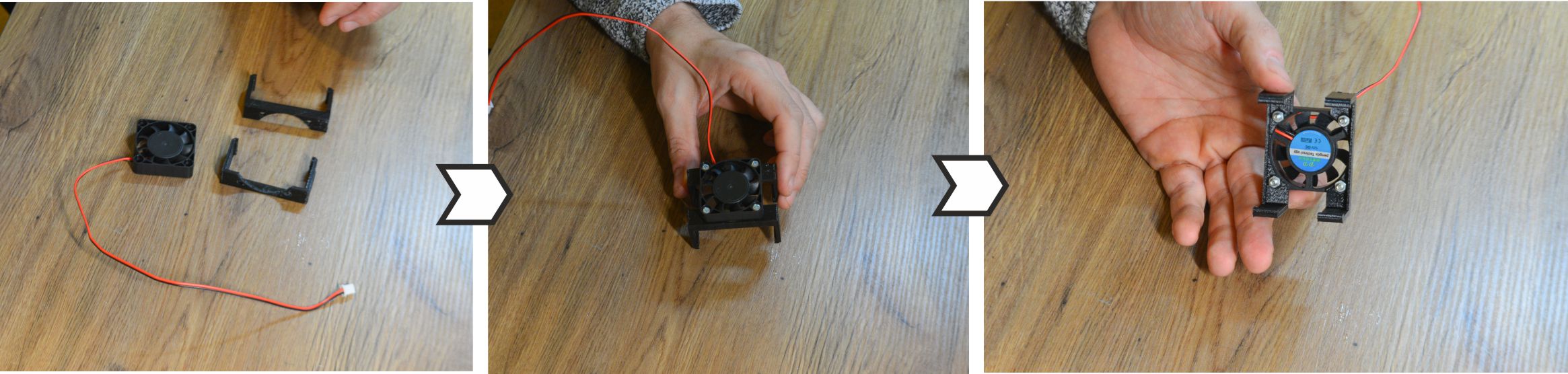
Above: Use 4x 15mm M3 bolts and 4 M3 nuts to fix the FAN to its support
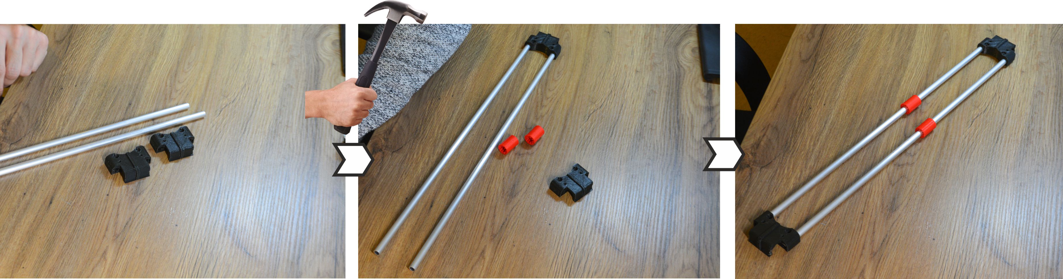
Above: Take the 2 aluminium pipes and insert both in the LATERAL SLIDER piece. This is the most important part of this assembly guide. It could seem quite hard to insert the pipes into the 3D printed parts, but the sturdiness of the structure will depend on how tight everything is. Use a hammer (gently) if you want to push the aluminium pipes into the channel. Twist the pipes as you are pushing them could help during the insertion. Before placing the second LATERAL SLIDER cap, insert the bushings (red in the photo above)
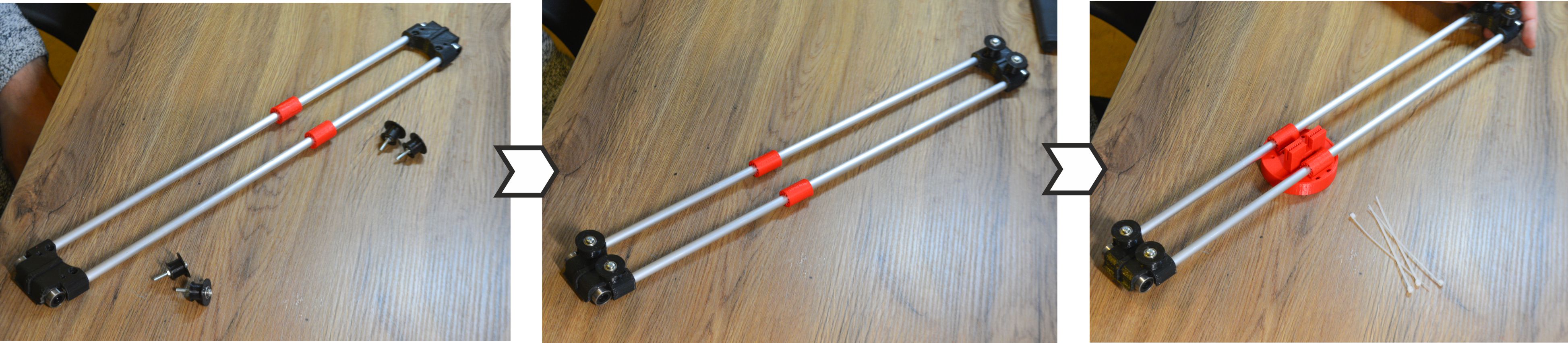
Now it is time to screw the pulleys you have assembled before. There is no need to use a nut to fix the bolts. Just screw them. Use zip ties to hold the pusher in place (x4). Just hug the plastic bushings with the zip ties as you run them through the pusher piece (there are two channels for that)
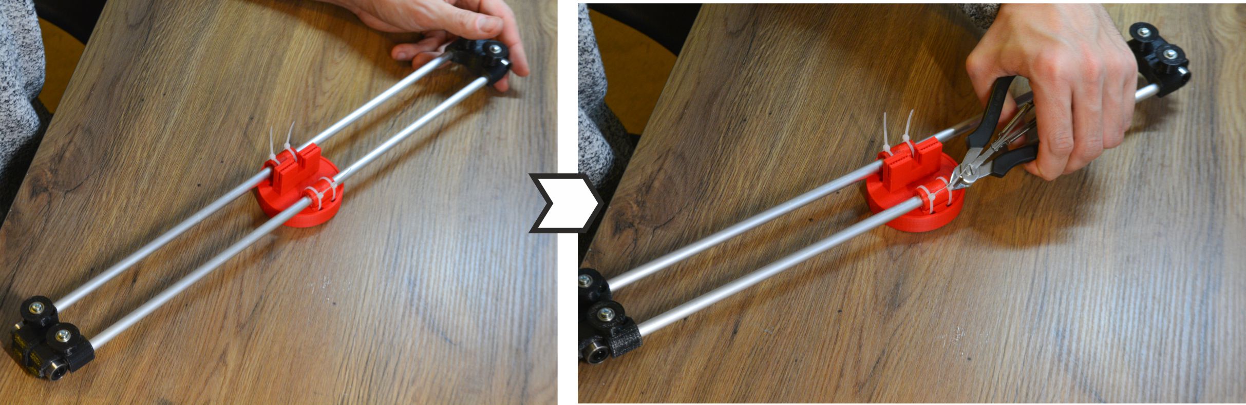
Cut the remaining zip ties.
Check there is not friction on this structure. Olive oil will greatly reduce the friction between the aluminium and PLA plastic.
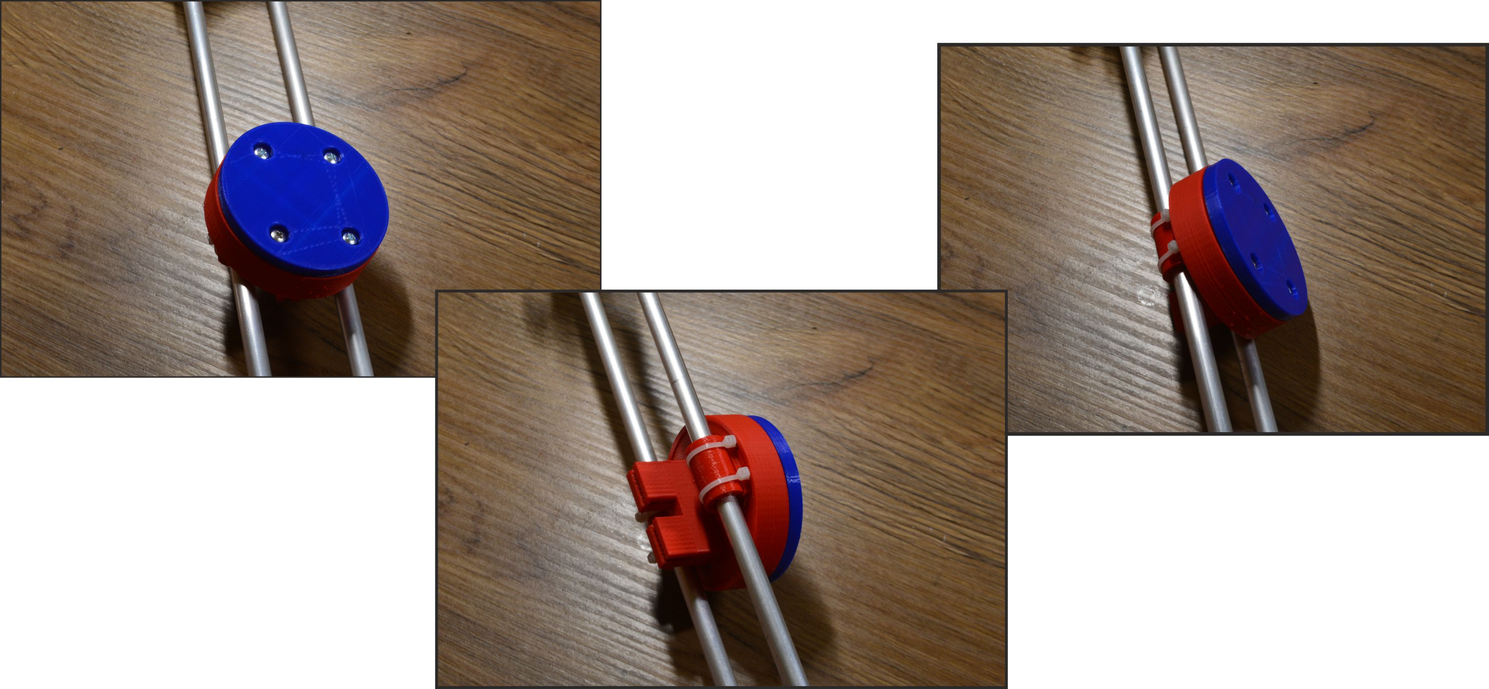
Use 4x 15mm bolts to fix the base of the PUSHER. All the photos above show how it looks after placing it
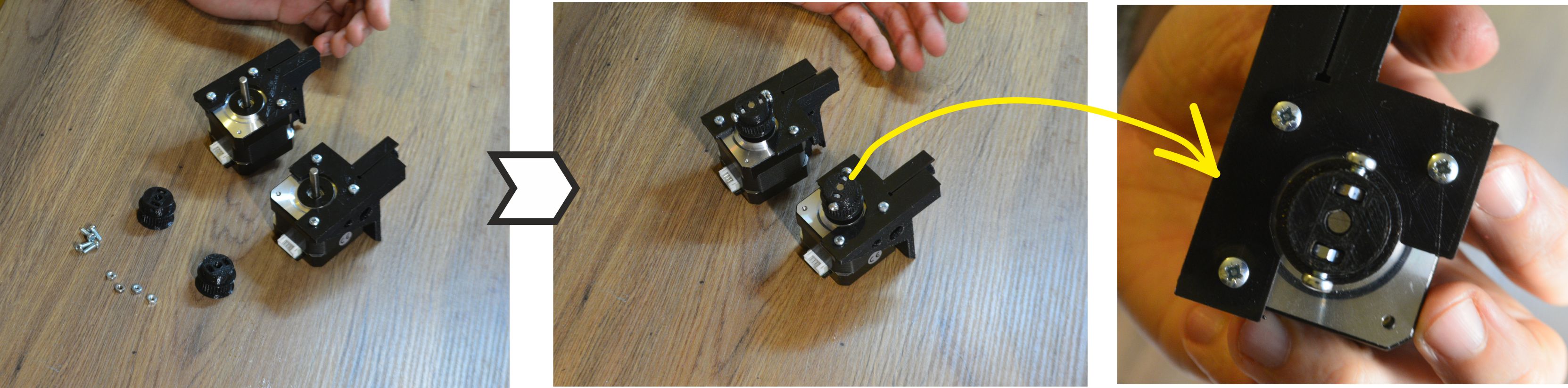
Now, take 4x M3 10mm bolts + 4 nuts to fix the pulleys to the motors axis. They have to be tight. These pulleys will transmit all the movement to the robot. If they are loose, the robot will misbehave.
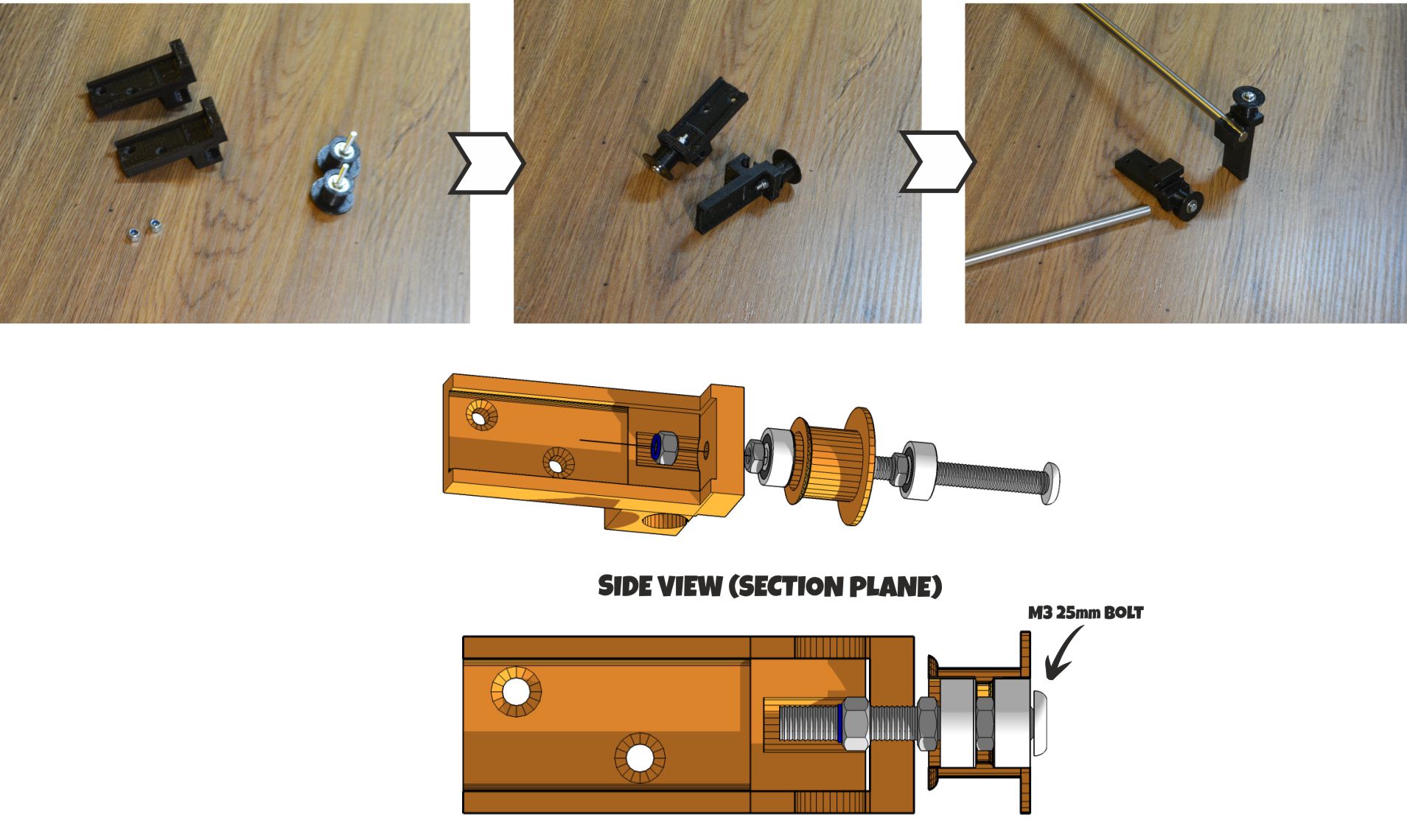
Above: side supports. Use a pulley (the ones with the 2x 623 ball bearings inside) and fix it the both side supports using a self-locking nut. Once finished, insert the steel bar into the side support.
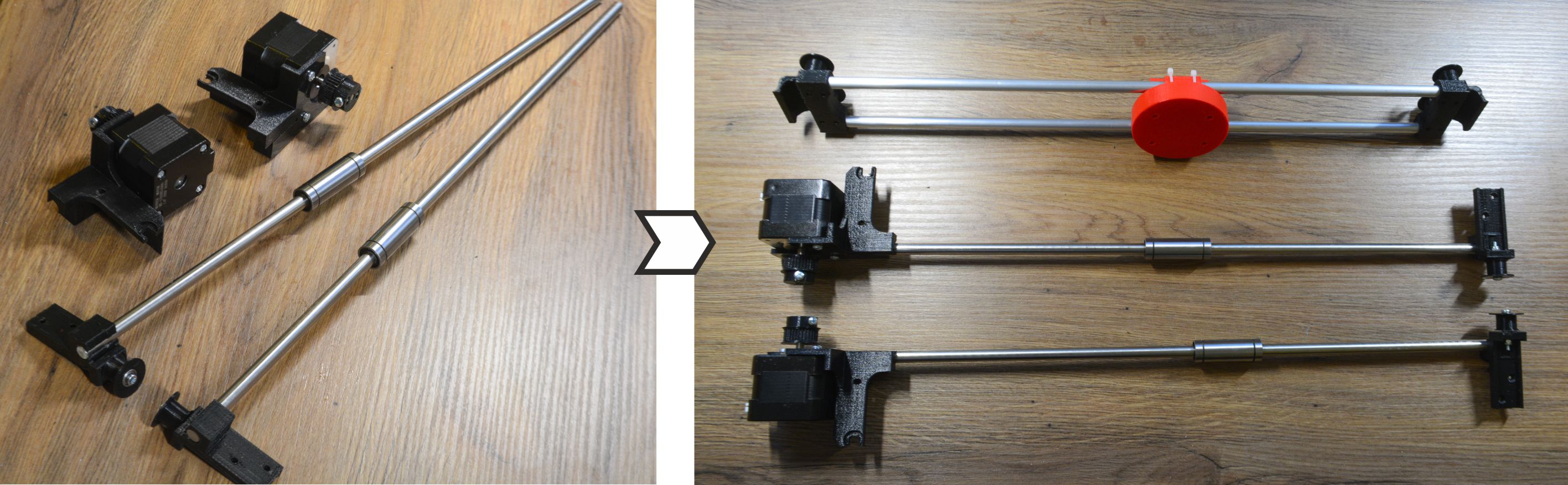
We are almost finished here. Insert the LM88UUs into the steel bars as indicated above. Do not forget this step! After placing the linear bearings (LM88UU), insert the steel bars into the motor´s support. Now you are ready to set everything on the Air hockey table.
Screw off the top screw and place the motor support in place.
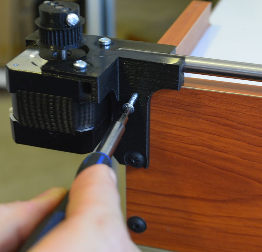 Once set, screw it again and use an extra wood screw to fix the motor holder.
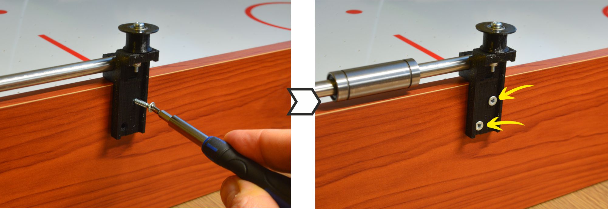 Fix the side support using to wood screws.
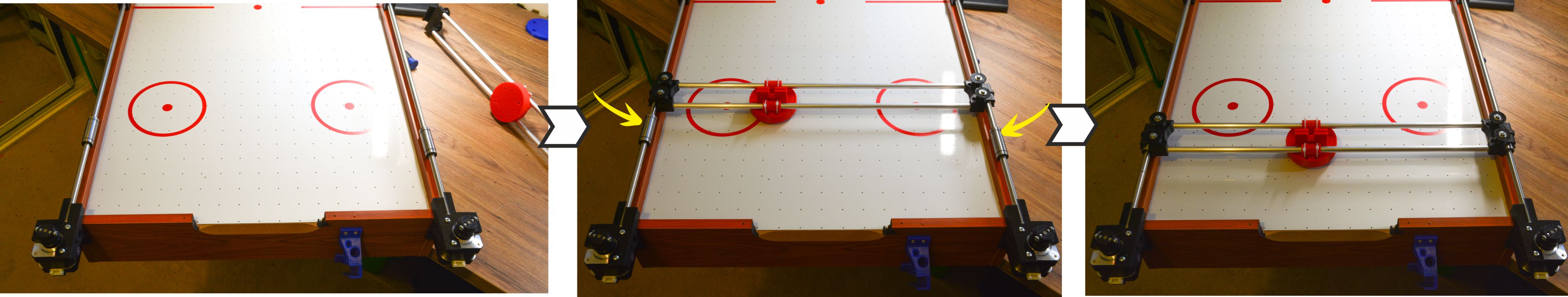
Push, gently, the X-axis robot structure into the LM8UU linear bearings. Check the video below
NOTE: If you find any burr inside the channel where the linear bearing is, remove it gently. Both LM88UUs have to be perfectly aligned in order to avoid any kind of friction with the steel.
2) HARDWARE:CONNECTING EVERYTHING
Electronics: Elements needed to control the Robot: jjRobots Brain Shield, Arduino Leonardo, 2x Stepper motor drivers (+heatsinks), FAN (12v) and 3D parts support + bolts/nuts
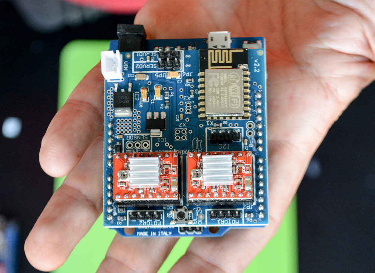
CLICK ON THE IMAGE ABOVE: All the electronics correctly set. Pay attention to the stepper motor drivers orientation.
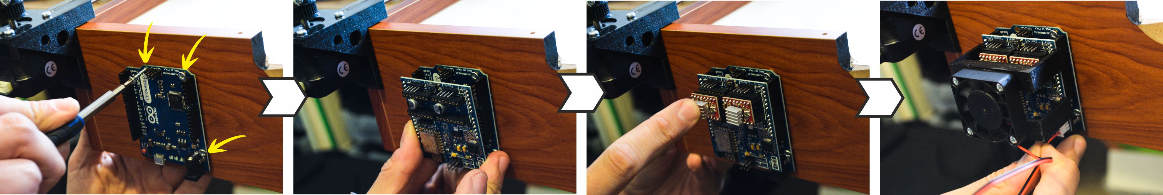
Above: Use 3 screws to fix the Arduino Leonardo to the Air hockey table (next to the motor). Then, connect the Brain Shield and finally, the stepper motor drivers.
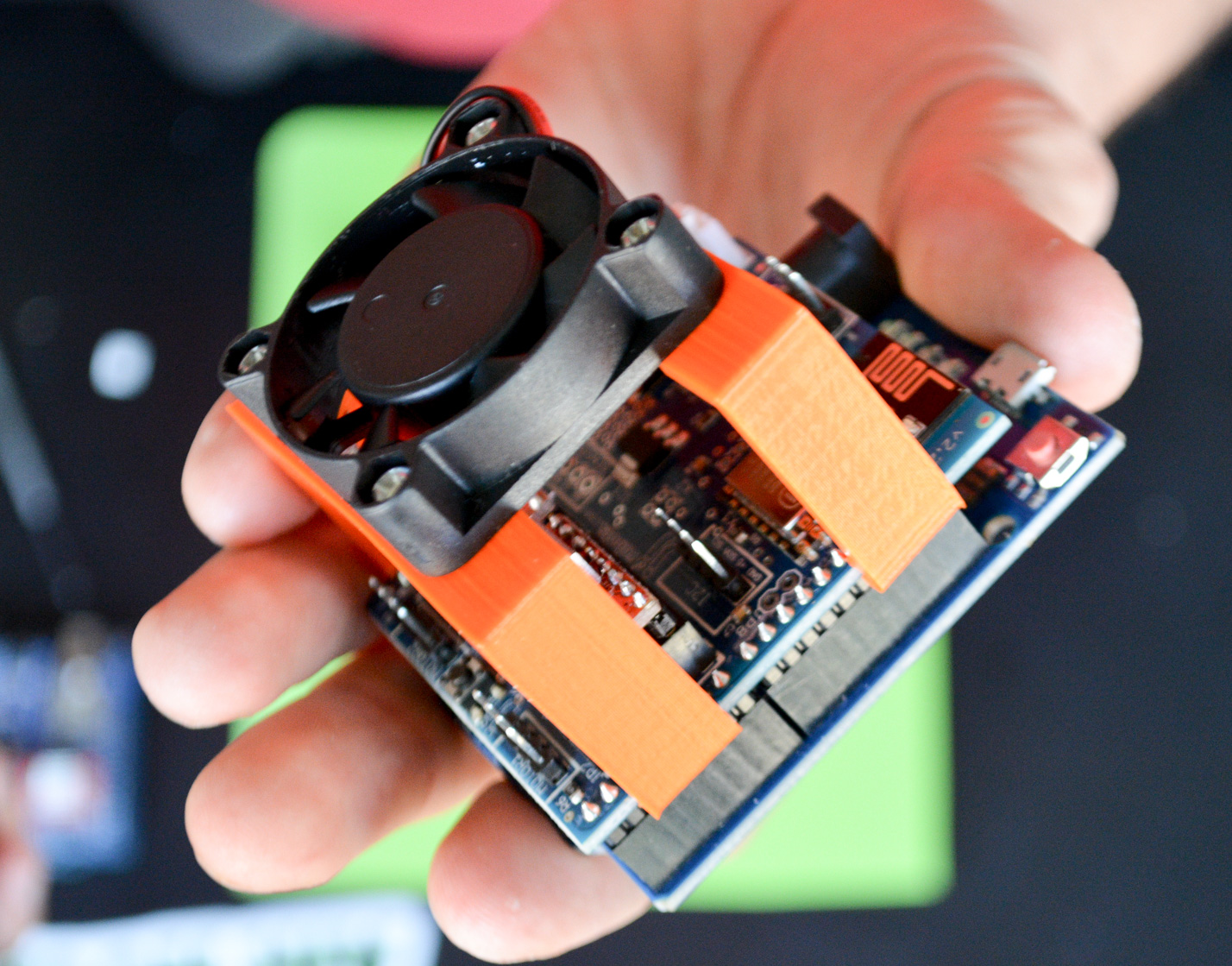
Above: detail of the electronics completely assembled and the FAN on top of everything
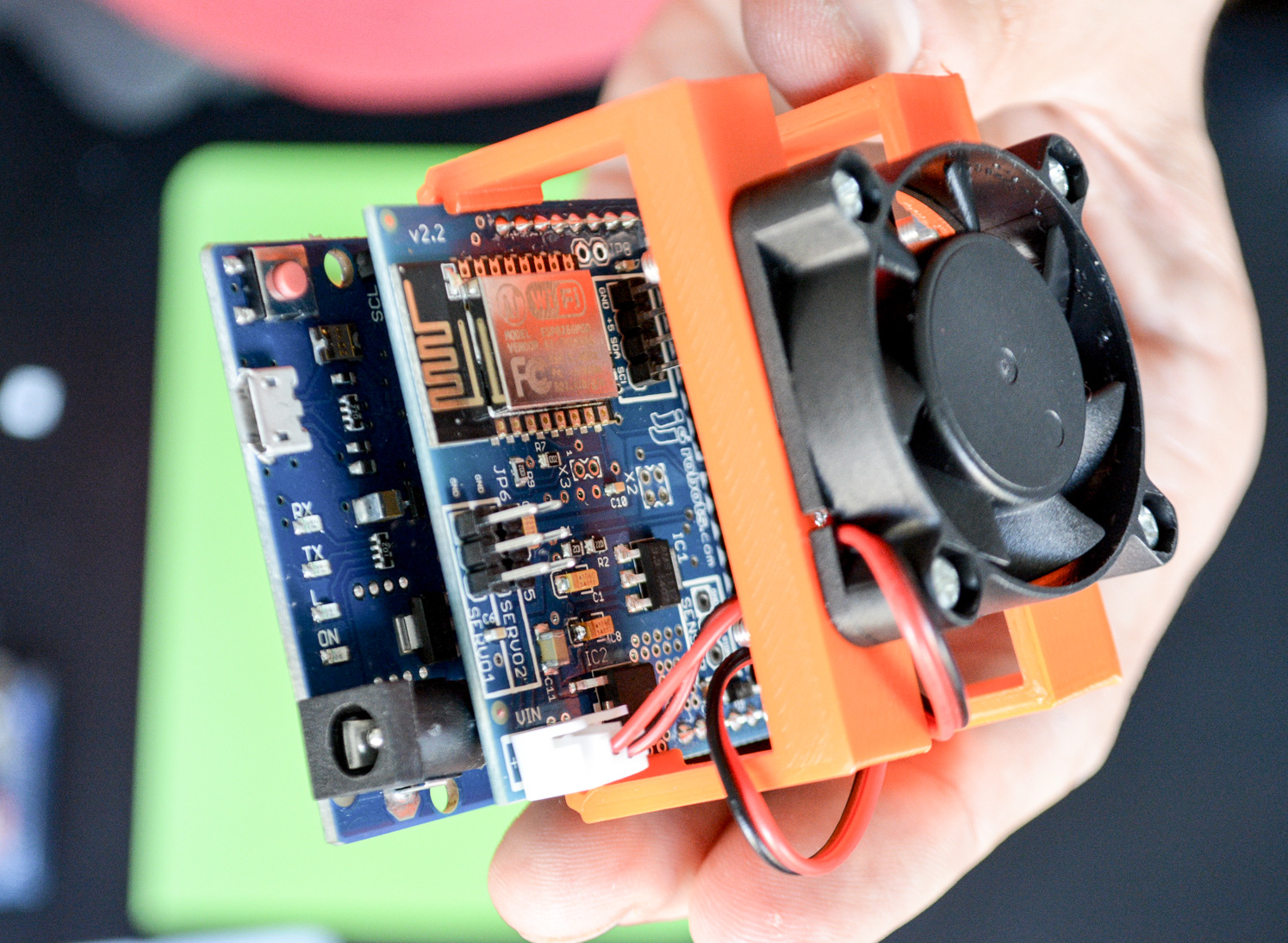
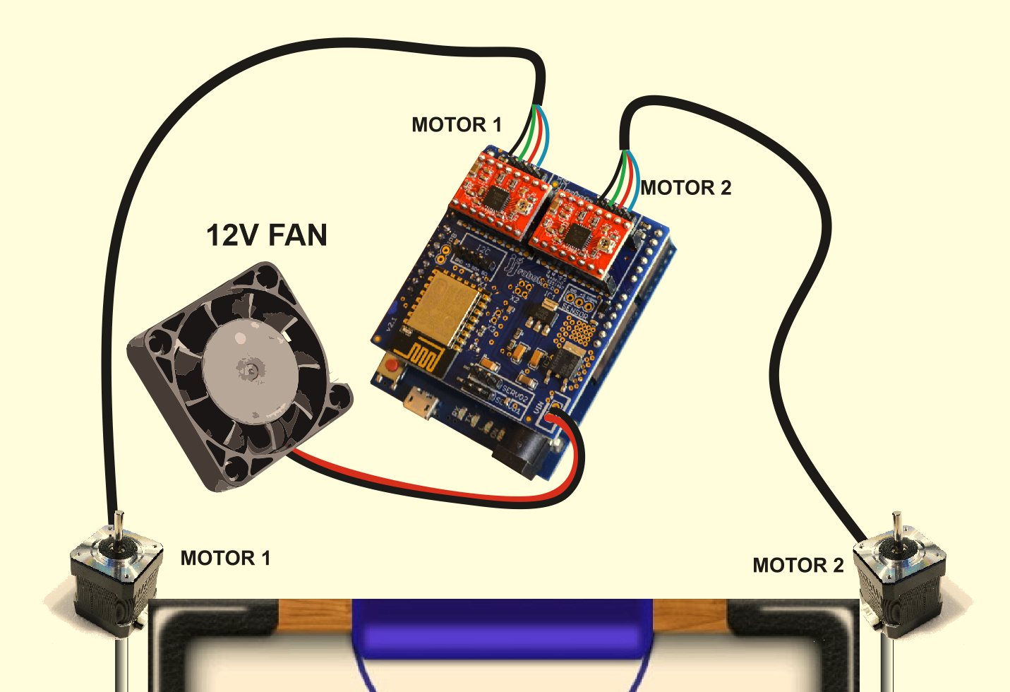
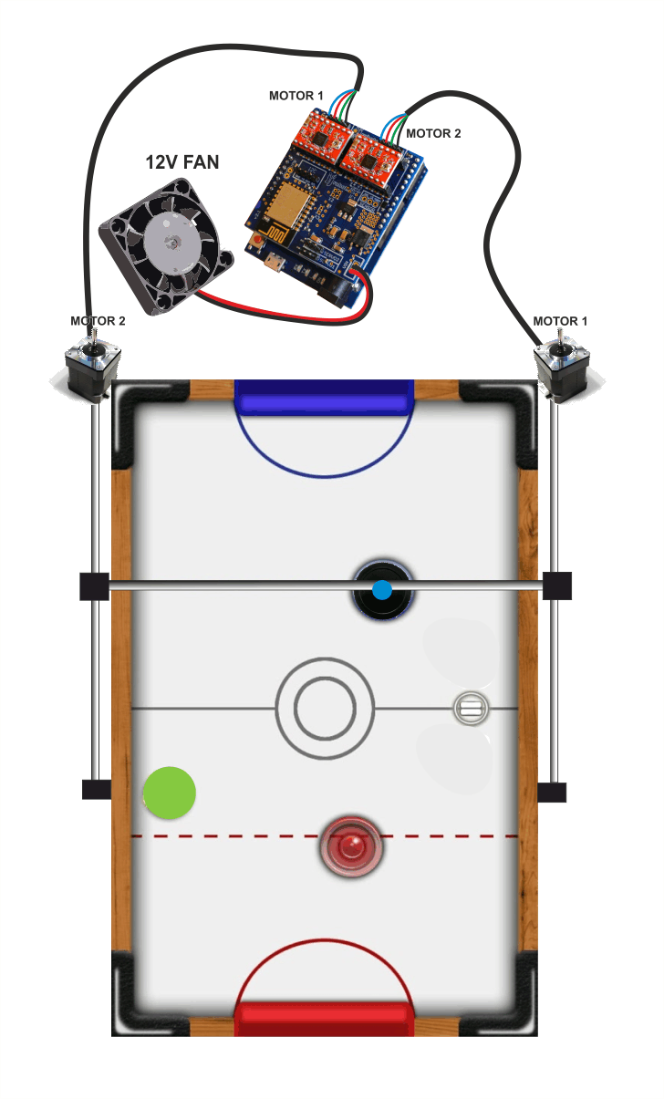
Connect the FAN to the VIN output of the jjRobots BRAIN SHIELD. There is only one way to connect it, but just in case, take a look to the electrical diagram below. And connect the motor cables.
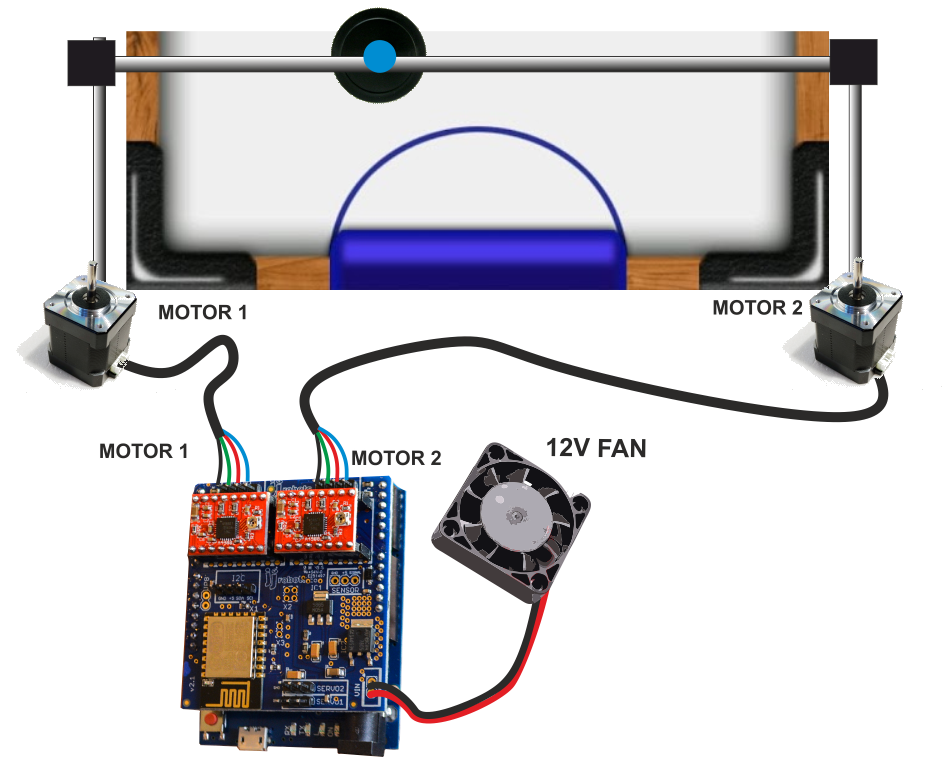
Above: How to connect all the cables. DOUBLE CHECK THE POLARITIES! The stepper motors can handle an inverted polarity but the FAN can not say the same.
Always, always keep the FAN blowing while the Air Hockey Robot is working. The stepper motor drivers might get damaged is there is not a constant air flow cooling them down

3) AIR HOCKEY ROBOT VISION SYSTEM ( YOUR SMARTPHONE)
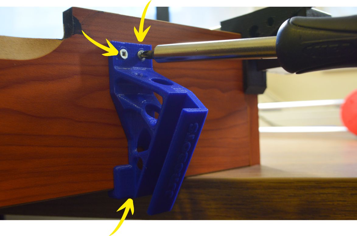
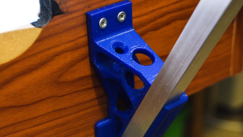
Use three screws (location indicated by the yellow arrow) to fix the POLE SUPPORT to the Air hockey table. Place it 2 cms away from the edge where the Air hockey table´s Goal will be placed.
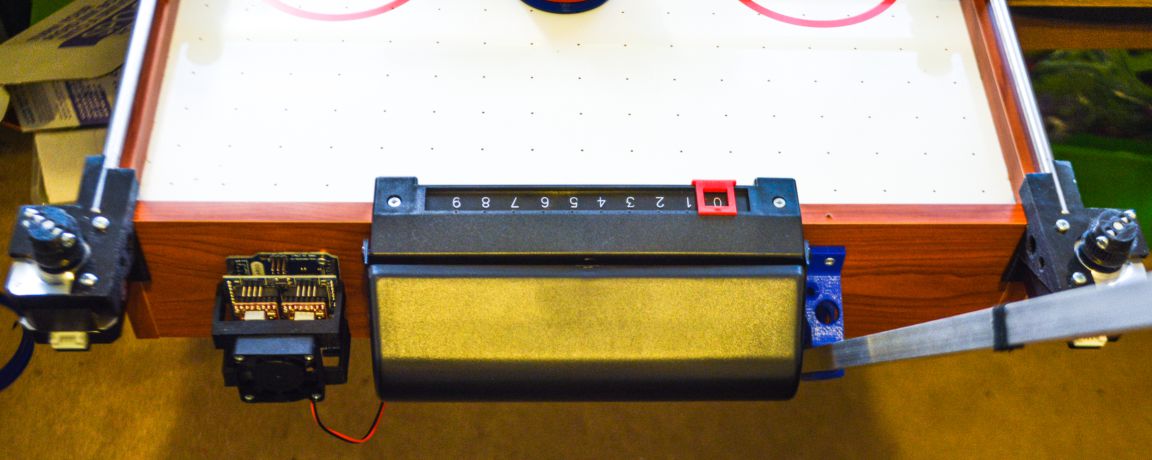
Now, if you set the GOAL in place, you should have something like the photo above (note: the motors are not connected in the photo)
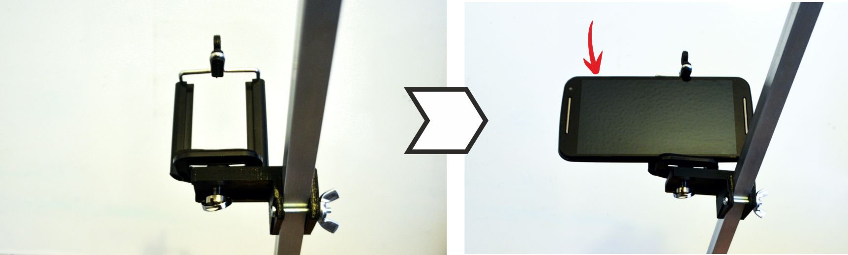
Use a 25mm long bolt and a wingnut to hold the smartphone support to the pole. Fix the smartphone holder using the camera bolt too. The camera of the smartphone has to be on the left side (pointed by the red arrow on the photo above)
Insert the pole into the pole support.
Above: the Control APP running and already calibrated. The first thing you have to do after placing the smartphone on the camera holder: calibrate the perspective. Try to have on screen as much air hockey playing court as you can. See the photo above.
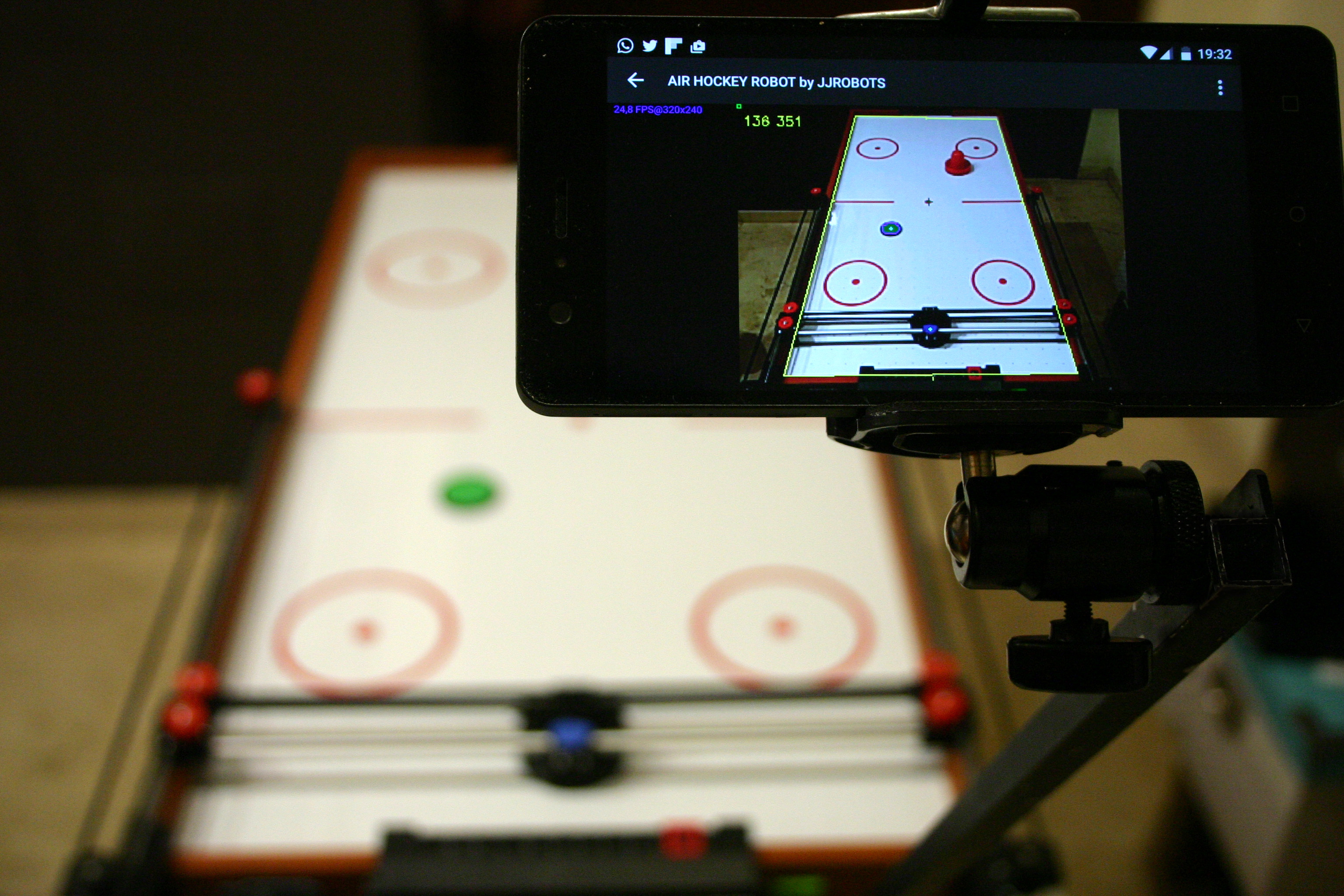
Above: the smartphone perfectly set to capture everything is happening on the playing court.
How to calibrate the perspective:
NOTE:
In order to connect the APP to the Air Hockey Robot, you will need to connect your smartphone to the “JJROBOTS_XX” WIFI NETWORK using the password: 87654321
CREATING THE COLOUR FEATURES (THINGS TO BE DETECTED BY THE ROBOT)
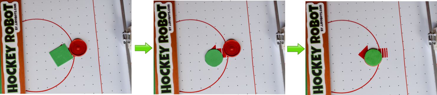
Cut the GREEN EVA foam with the shape of the PUCK (use it to draw its shape on the foam and then cut it). Stick it to the PUCK using the double side tape provided
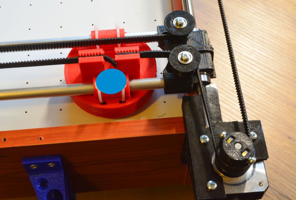
Cut a 20mm diameter circle of BLUE FOAM and place it as above. Use the double side tape to stick it.
Why using FOAM and not a 3D printed feature or…a sticker?
Due to the FOAM anti-reflective capacity. Keep in mind that the ROBOT VISION SYSTEM can be tricked by FAKE reflections on a plastic surface. The ROBOT is not just detecting a colour but two features: SIZE AND COLOUR
An uniform illumination is extremely important for the vision system. Avoid shadows, reflections (and if you can, fluorescent lighting).

4) PROGRAMMING THE ARDUINO LEONARDO
STEPS:
- Download the ARDUINO CODE from HERE (or go to jjRobots GITHUB REPOSITORY and download it from there)
- Connect the USB cable provided to the Arduino LEONARDO
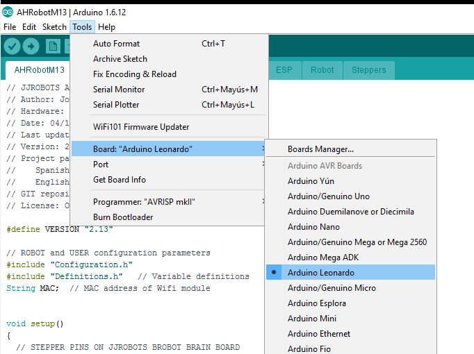
- Compile the CODE using the ARDUINO IDE (The CODE is compiling and has been tested under ARDUINO IDE 1.6.12) and upload it
(Below:You have to select the ARDUINO LEONARDO as the default board and its PORT in the “TOOLS” MENU)
5) CHECKING THE ROBOT H-BOT AND MOTORS
Well, it is time to check the Robot movement skills. The jjRobots Brain Shield has a button placed between the motors connectors: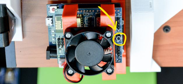
Push it if you want the robot to make a MOVEMENT TEST PATTERN . This will let you know if everything is fine with the structure and motor control. This is the first time you will see how the robot moves by itself, so do not place anything on the air hockey table and be careful with your fingers!
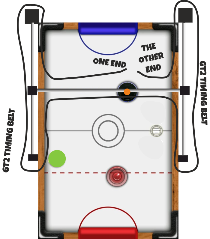
BEFORE TURNING IT ON: PLACE THE TIMING BELT IN THE H-BOT STRUCTURE. IMPORTANT: DO NOT TIGHTEN THE BELT TOO MUCH, CONTRARY TO THE “LOGIC” A VERY STIFF BELT WILL NOT LET EVERYTHING TO MOVE SMOOTHLY
Above: How to run the timing belts around the H-BOT structure
Above: details of both ends of the timing belt inserted into the PUSHER
If your robot is not making the TEST pattern, read below and find your problem:
- The robot is crashing against one side of the air hockey table: check the polarity of the motor cables.
- I am hearing a cracking noise coming from the motor/s and the robot does not move at all or not enough to draw the pattern: the stepper motors can not move the robot due to lack of power. This can be caused by:
- There is too much friction in the H-bot structure: Check everything again. Is the timing belt too tight?
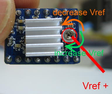
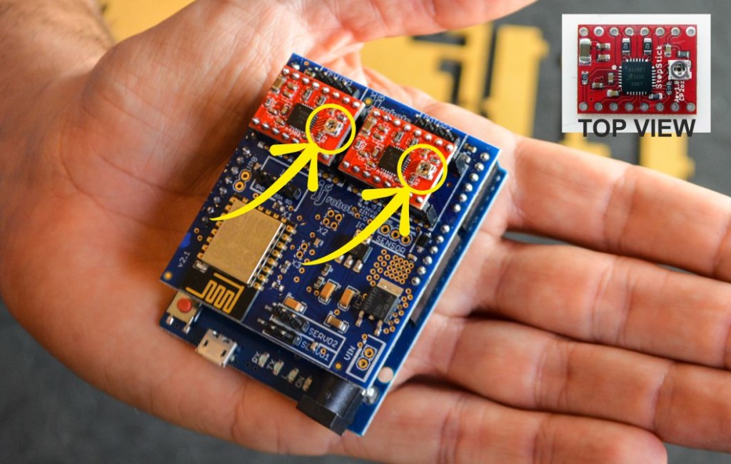
- Try to adjust the STEPPER MOTOR DRIVERS output current via its potentiometer
The Air Hockey robot uses two powerful stepper motors. Keep an eye on where you place your fingers!.
Sudden accelerations of the robot within its playing area could catch you unaware. Before adjusting anything remember to disconnect its power supply.
TROUBLESHOOTING
- The robot is crashing against one side of the air hockey table: check the polarity of the motor cables.
- I am hearing a cracking noise coming from the motor/s and the robot does not move at all or not enough to draw the pattern: the stepper motors can not move the robot due to lack of power. This can be caused by:
- There is too much friction in the H-bot structure: Check everything again. Is the timing belt too tight?
- Try to adjust the A4988 STEPPER MOTOR DRIVERS output current via its potentiometer:
LINKS: