HOW IT WORKS HOW TO CREATE ONE? LASER POINTER FORUM

Steps to play with it:
1) Place the Laser GUN wherever you want (in the range of the WIFI, it can be 60 meters away!)
2) Use your Smartphone/Tablet to control the laser/torch
3) Have fun! (no one will ever know who is controlling that laser/torch located on the top of the tree!)
USE nº1:
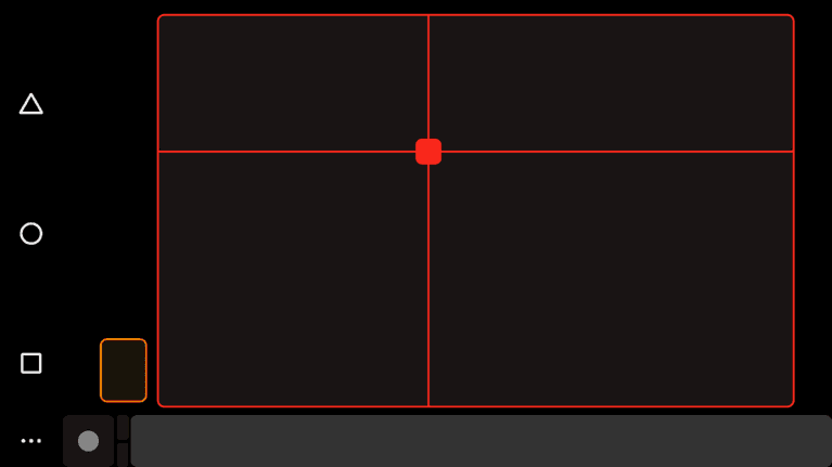
Try to aim the laser with just one tap on the smartphone screen exactly where you want to
USE nº2:
Perfect for my cat! Why not automate this to make my cat play every….uhh…6 hours? Fetch the point!

How does it work?
Laser pointer is a remotely controlled arduino robot created with 3D printed parts. With only two servos, this robot is able to point any object in the X and Y axis. The amplitude of the movement can be configured in the CODE. You can control its movements by sending commands through a Smartphone, Tablet or PC WIFI. The maximum signal range is up to 50-60 meters.
They are small in size but pack a big punch and are very energy efficient. Because of these features, they can be used to operate remote-controlled or radio-controlled toy cars, robots and airplanes. Servo motors are also used in industrial applications, robotics, in-line manufacturing, pharmaceutics and food services. But how do the little guys work?
| To fully understand how the servo works, you need to take a look under the hood. Inside there is a pretty simple set-up: a small DC motor, potentiometer and a control circuit. The motor is attached by gears to the control wheel. As the motor rotates, the potentiometer’s resistance changes, so the control circuit can precisely regulate how much movement there is and in which direction.When the shaft of the motor is at the desired position, power supplied to the motor is stopped. If not, the motor is turned in the appropriate direction. The desired position is sent via electrical pulses through the signal wire. The motor’s speed is proportional to the difference between its actual position and desired position. So if the motor is near the desired position, it will turn slowly, otherwise it will turn fast. This is called proportional control. This means the motor will only run as hard as necessary to accomplish the task at hand, a very efficient little guy. |
How is the Servo Controlled?
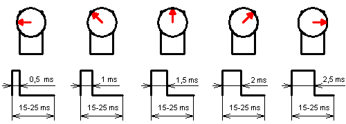
Servos are controlled by sending an electrical pulse of variable width, or pulse width modulation (PWM), through the control wire. There is a minimum pulse, a maximum pulse and a repetition rate. A servo motor can usually only turn 90° in either direction for a total of 180° movement. The motor’s neutral position is defined as the position where the servo has the same amount of potential rotation in the both the clockwise or counter-clockwise direction. The PWM sent to the motor determines position of the shaft, and based on the duration of the pulse sent via the control wire the rotor will turn to the desired position. The servo motor expects to see a pulse every 20 milliseconds (ms) and the length of the pulse will determine how far the motor turns. For example, a 1.5ms p
ulse will make the motor turn to the 90° position. Shorter than 1.5ms moves it to 0° and any longer than 1.5ms will turn the servo to 180°, as diagramed below.
The servo circuitry is built right inside the motor unit and has a positionable shaft, which usually is fitted with a gear (as shown below). The motor is controlled with an electric signal which determines the amount of movement of the shaft.
What’s Inside the Servo?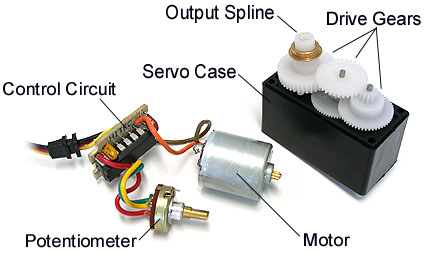
The “insides” of a servo motor (Left) and an assembled servo (Right)
When these servos are commanded to move, they will move to the position and hold that position. If an external force pushes against the servo while the servo is holding a position, the servo will resist from moving out of that position. The maximum amount of force the servo can exert is called the torque rating of the servo. Servos will not hold their position forever though; the position pulse must be repeated to instruct the servo to stay in position.
Now… How to create a remotely controlled laser pointer
FIRST
COMPONENT LIST:
- jjRobots electronic brain shield (the same Shield you have already used for all the jjRobots projects –Brobot ,iBoardBot, Sphere-o-bot or any other jjRobot-)
- An inexpensive laser/LED torch (like this one)
- The 3D printed parts. You have two options:
- Print the support parts + CASE
- Use the CASE we provide with our robotics KITs and only print the support parts. If you need the STL models, click here
- Arduino LEONARDO (Arduino ONE will do the job too)
- 2x SG90 SERVOS (they are standard, easy and inexpensive to get)
- 12V power supply (actually, from 9 to 12 volts will work). If you want to make it portable, use a 9V battery
SECOND
PROGRAMMING THE ARDUINO
a) Install the Arduino IDE on your PC from (skip this step if you have arduino already installed)
This B-robot code has been tested and developed on IDE version 1.0.5
b) Install the libraries (https://github.com/jjrobots/B-ROBOT/tree/master/libraries)
Copy the folders inside the /libraries into the Arduino/libraries folder on your hard drive and restart the Arduino IDE
JJROBOTS_BROBOT
JJROBOTS_OSC
c) Get the main CODE: LaserGUN with PRO MODE (.zip file)
d) Compile and send the code to the Arduino Leonardo
- Open your Arduino IDE
- Open the main code LaserGUN.ino
- Connect your Leonardo board with the USB to the PC
Note: If this is the first time you connect a Leonardo board to your PC maybe you will need to install the driver.Select the board Leonardo (tools->board)
-Select the serial port that appears on the tools->Serial port
-Send the code to the board
THIRD
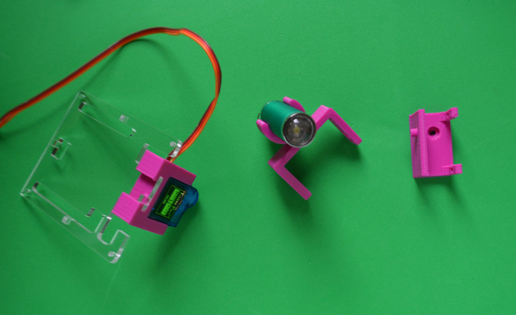
ASSEMBLING THE TORCH/LASER POINTER
Using the acrylic case (if you got any of the jjRobot´s robotics KITs):
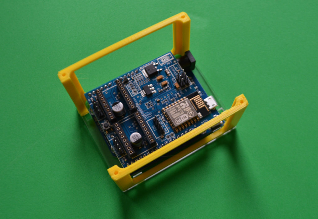
Above: Fix the Arduino Leonardo + jjRobots Brain Shield to the bottom of the case using 3 short bolts + nuts. Do the same with the plastic laterals as shown above.
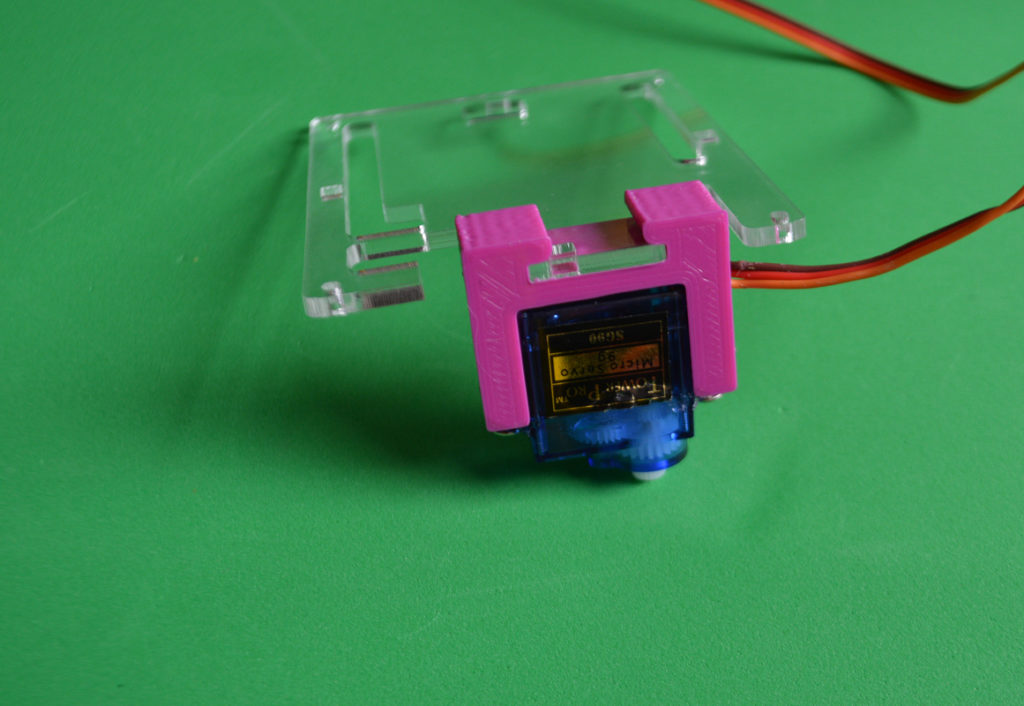
Above: Fix the “BASE” servo to the support piece and attach both to the acrylic TOP lid. Use two screws to fix the servo to the plastic holder.
Above: This is how it looks now. If you want place the torch on its holder now
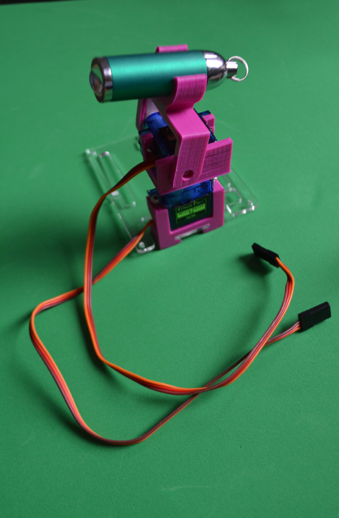
ABOVE: Assemble the plastic parts as indicated. For this, we have placed the servo´s arm inside the existing hollows (that will avoid the servo´s arms to skip) and fixed using the remaining screws. Keep in mind, everything should be rotating freely. NOTE:You might need to re-adjust the rotational limits of the mentioned arms once the torch/laser pointer is working.
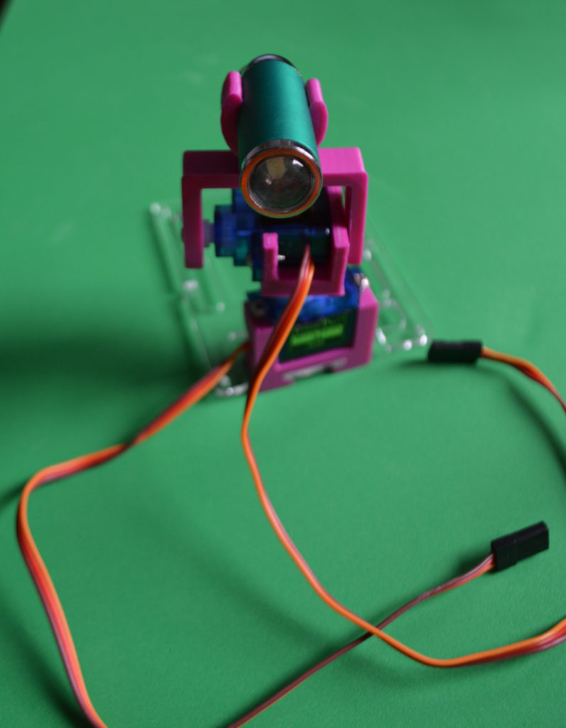
Detailed photo
This is where we are now. Almost ready to play with it.
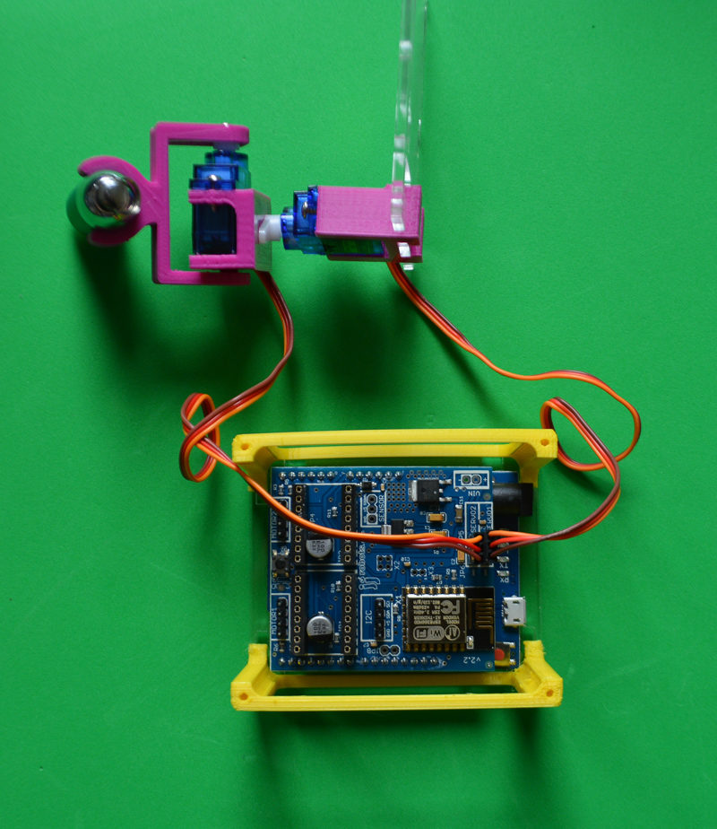
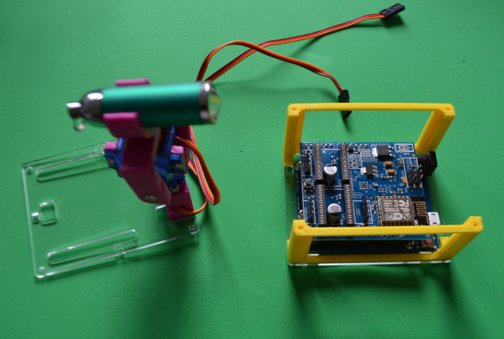
Connect the top Servo to the SERVO2 header on the jjRobots Brain Shield
Connect the base servo to the SERVO1 header
And… fix the top lid to the case using 4 bolts. Now you are ready to play with it. Jump to the assembly step FOURTH
FOURTH
Check everything again (just in case) : Voltage polarities, signal wires…
FIFTH
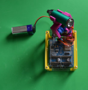
Connect the Leonardo to the battery or an external power supply to the Arduino (from 7 to 9 will be ok)
NOTE: If you got the “MOST AWESOME ROBOTICS KIT” you can use the battery holder provided.
SIXTH
Controlling the LASER GUN via WIFI:
1) Connect your device to the new WIFI network: “JJROBOTS”
NEW: control your robot using the FREE JJrobots google APP! (android devices)
![]()
To control the LASER GUN, we use OSC protocol over an Internet connection (Wifi module) using UDP packets or the jjRobots official APP (free). Both are a lightweight and efficient way to send commands to our Robots.
Advantages of the TouchOSC: We could also personalise the Interface we are using in our device so we will be able to control anything! What we need to do is to implement a lightweight library for Arduino in order to support this protocol (easy). We only use a subset of the OSC protocol to keep things small.
LINK: LASER GUN REMOTE CONTROL LAYOUT PRO MODE for OSCtouch software (Android Version/ iOS version)
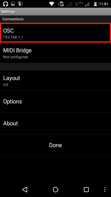
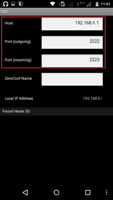
Setting up the TouchOSC software:
If you are going to use the Touch OSC software to control the LASER POINTER, you will need to set these parameters in the TouchOSC like this:
HINT:
How to modify the amplitude of the laser (servos) movements
Inside de ARDUINO CODE, at the beginning, you will see these text lines:
// Normal servo range (servo goes from SERVO_NETRAL – (SERVO_RANGE/2) to SERVO_NEUTRAL + (SERVO_RANGE/2)
#define MAX_SERVO1_RANGE 600
#define MAX_SERVO2_RANGE 400
//These are the values (in red) that determine the amplitude of the movement. If you have a small screen, could be better to set smaller values
// Range when PRO mode is pressed (usually more servo range)
#define MAX_SERVO1_RANGE_PRO 1000
#define MAX_SERVO2_RANGE_PRO 1000
With the same electronic and some other parts (stepper motors) you can create your own B-robot (the self balancing robot!)
Some info was taken from: http://www.jameco.com/jameco/workshop/howitworks/how-servo-motors-work.html