ASSEMBLY TIME: 30-40 minutes
Tools needed: Phillips screwdriver
TROUBLESHOOTING AIR HOCKEY FORUM KNOW HOW GITHUB
BILL OF MATERIALS:
- 12x M3 bolt 6mm
- 4x M3 bolt 10mm
- 6x M3 bolt 15mm
- 4x M3 bolt 20 mm
- 16x M3 nut
- 2x M3 self blocking nut
- 10x M2.5 Wood screw 20 mm
- EVA FOAM (two different colours)
- 4cm 12V FAN
- 2x Stepper motor NEMA17 + cables (70+70 cms)
- jjRobots Brain Shield
- Arduino Leonardo
- 1x Playstation 3 EYE CAMERA
- 2x Stepper motor drivers A4988 + heatsinks
- 12V 2A power supply 5.5mm 2.5mm jack
- 6x LMU88 linear ball bearing
- 12x 623 ball bearings
- 2x Stainless steel bar 8⌀ 450mm long
- 2x Anodised aluminium tube 8⌀ 390 mm long
- 1x Aluminium square pipe 12×12 mm 80cm
- GT2 timing belt (280 cm)
- 5x zip ties (150mm x 3 mm)
- double side sticky foam
- 3D printed parts
- AA alkaline batteries
- Air hockey table
LINKS
SHORT INTRODUCTION:
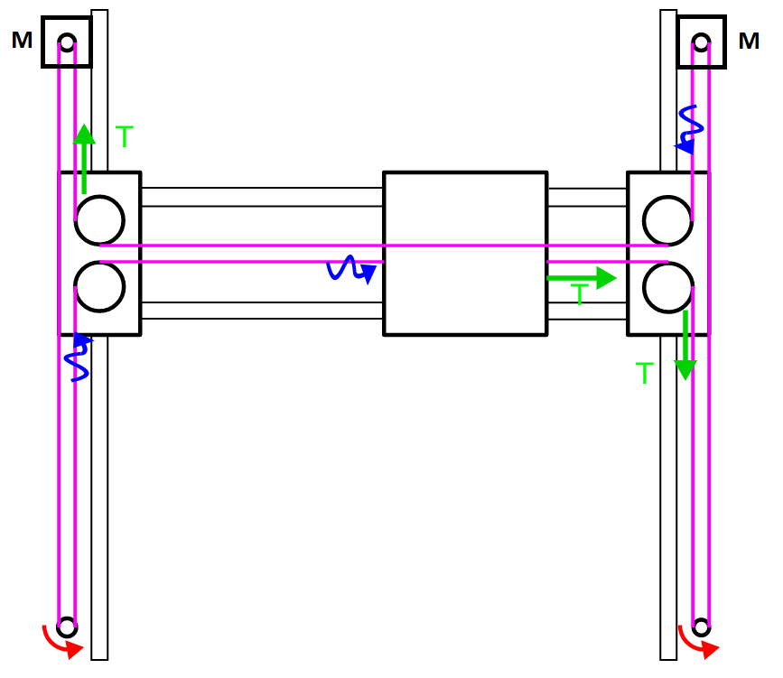
If you got the AIR HOCKEY ROBOT KIT you already have everything you need to create the robot. This will take no more than 30-40. The key for assembling a flawless working robot is the H-bot system: this structure allows the robot to move itself to any location on its playing field only using two motors. Can be detached easily so you can use the Air Hockey robot as a Air hockey table whenever you want.
You need this H-bot to run smooth and be strong at the same time. The better you set it up, the higher the accelerations you can reach with your robot. Pay attention to the tips provided throughout this guide.
The other thing to be aware of: vision system. The camera is capable of capturing 60 frames per second. Doing that, the robot can calculate precisely the position (and in consequence, its trajectory ) of both the robot and the puck.
This guide is fulfilled with tips, videos (they help a lot) and comments about how this robot works. The COMMUNITY will help you (and others) to find solutions to the issues that always arise. Keep in mind that this is an OPEN SOURCE robot, so feel free to try hack/modify it as much as you want. All the CODE has been commented and all the files/3D models are completely available.
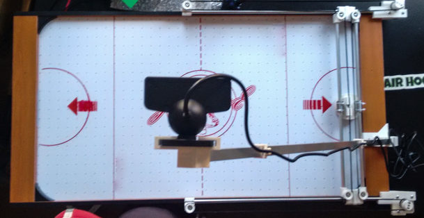
AIR HOCKEY ROBOT: HOW DOES IT WORK? (SHORT VERSION)
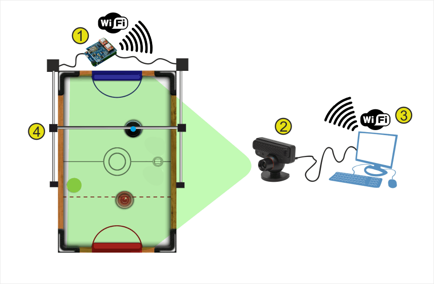
Above, the Air hockey robot. Mounted on the Air hockey table, this robot is always connected via WIFI to a computer (3), exchanging information about how to control the motors which are in charge of moving the robot (4).
There is a camera looking at the playing court (2). The camera´s captured data is sent in real time over the WIFI to the computer (3) where the data is processed.
(3) The computer reads that information from the camera, detects the position of the puck (green circle) and the pusher robot (blue small spot in the image above) and according to the current status of all the elements on the court, sends the control information to the (1) jjRobots Brain Shield (in charge of moving the robot)
Then, jjRobots Brain Shield (1),dictates the speed and acceleration of the robot, sending the appropriate pulses to the stepper motors. Easy!
VISION SYSTEM: The coordinates of the puck and its trajectory are calculated using the visual data coming from the camera (2). Two consecutive frames are required in order to calculate the trajectory of the puck. The Air hockey robot uses its current location, the puck position and the trajectory prediction to determine its strategy – either defence, defence and attack, or a new attack. An uniform illumination is extremely important for the vision system. Avoid shadows, reflections (and if you can, fluorescent lighting).

The Air Hockey robot uses two powerful stepper motors. Keep an eye on where you place your fingers!.
Sudden accelerations of the robot within its playing area could catch you unaware. Before adjusting anything remember to disconnect its power supply.
ASSEMBLING THE H-BOT
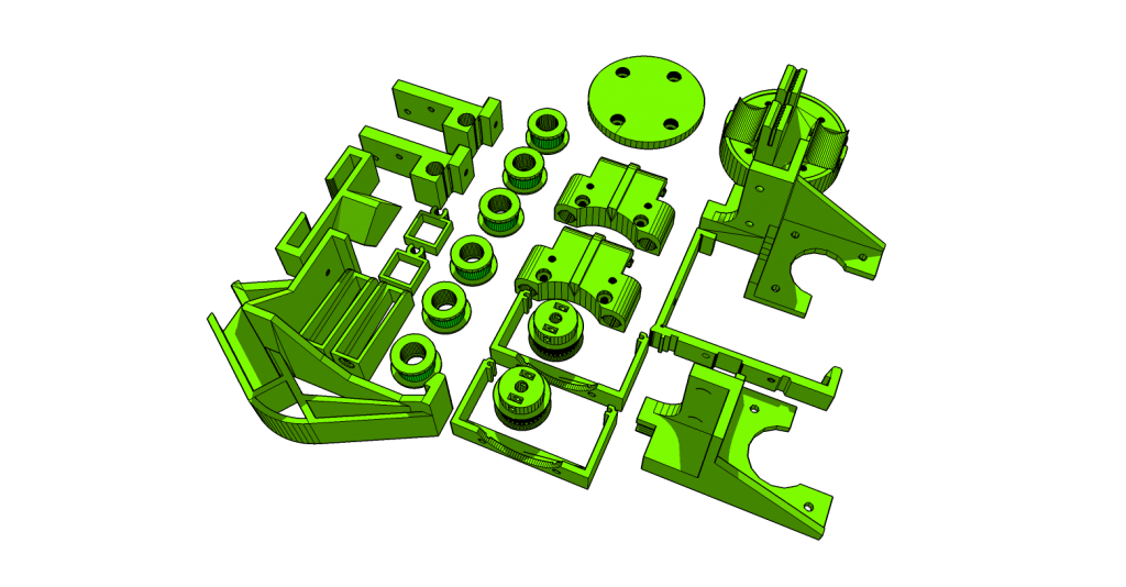
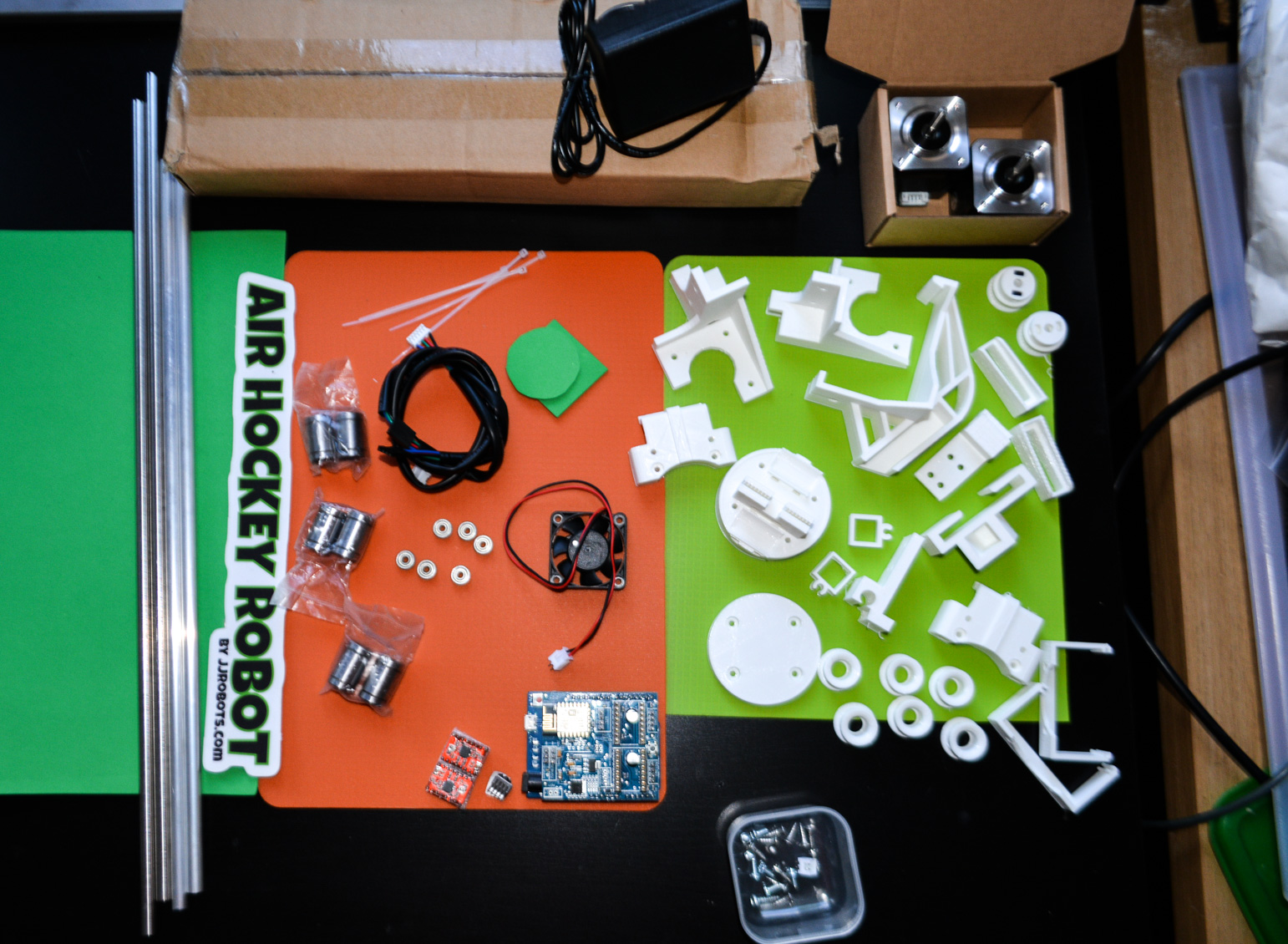
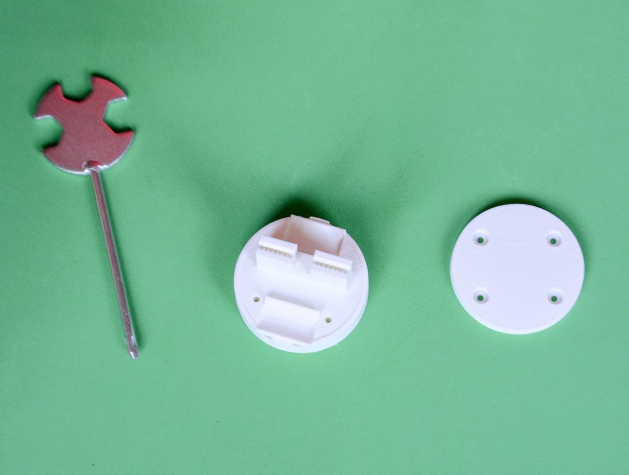
Gather all the 3D printed parts
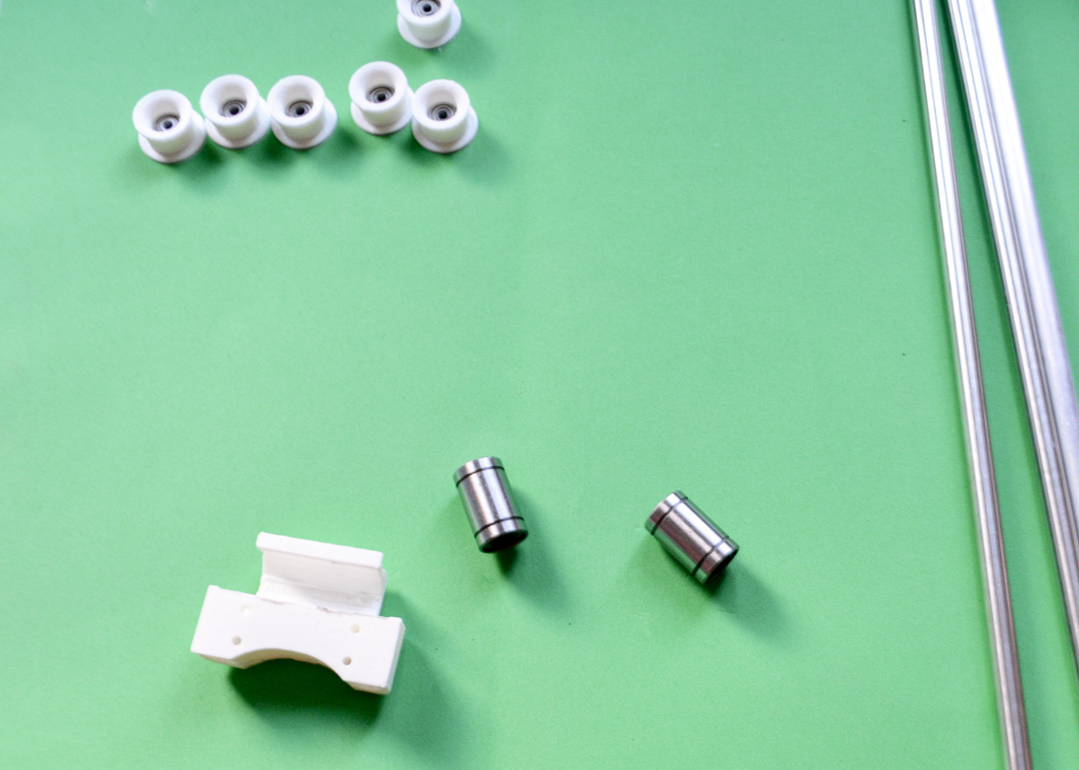
Place the 623 ball bearing (12 units, 2 per pulley) inside the plastic pulleys (top on the photo above) and pick the LMU88 linear bearings and the piece shown in the photo (white)
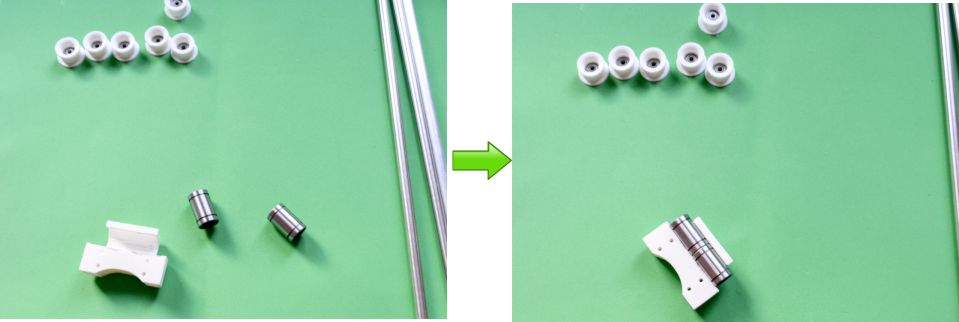
Push the LMU88 into the plastic part. If you find any burr or inside the channel where the linear bearing is, remove it gently. Both LMU88s have to be perfectly aligned in order to avoid any kind of friction with the steel bar that will run inside.
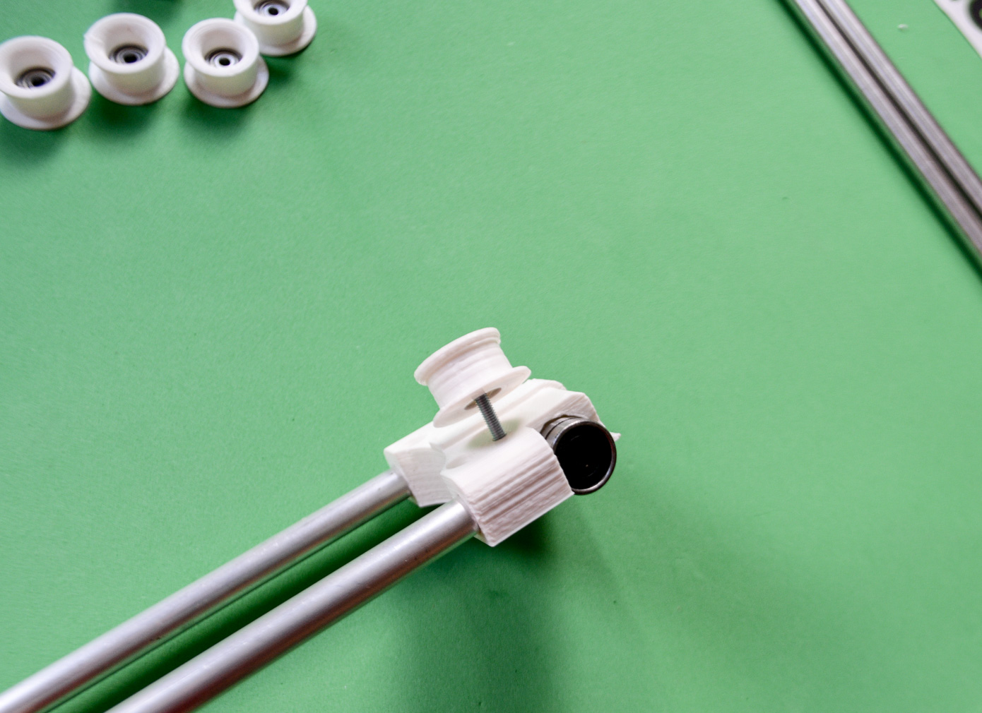
Insert both ALUMINIUM tubes (8⌀ 390 mm long) inside the plastic part (LATERAL SLIDER)
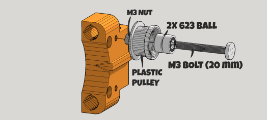
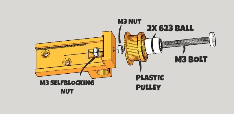
Assembly the pulleys (two per lateral slider) as indicated above. Avoid any friction here. This is important. The pulleys should rotate without resistance (see the video below)
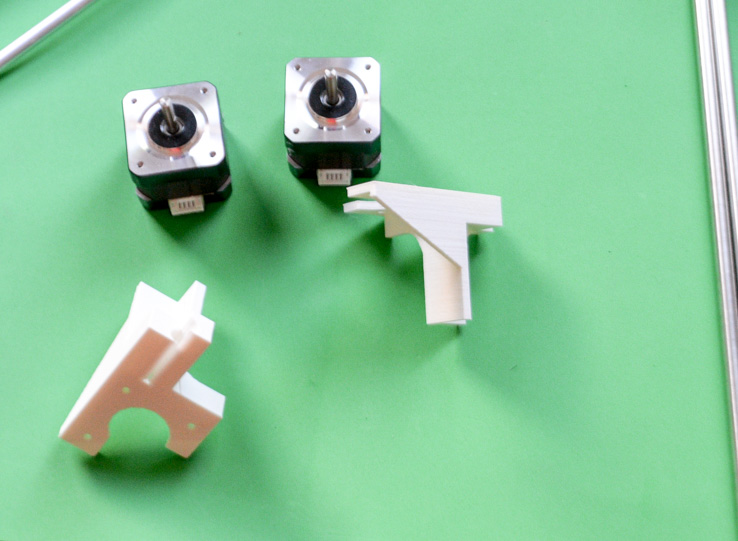
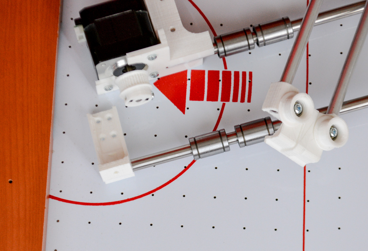
Time to fix the stepper motors. Take the parts indicated above, 6x M3 6mm bolts, 4x M3 10mm bolts and 10x M3 nuts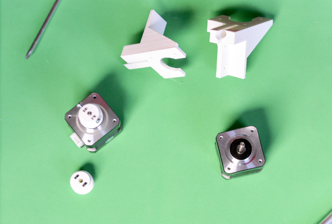
Put inside the holes of the pulleys the M3 nuts and use the 10mm bolts to fix the axis. You would need a hammer to push the pulleys in place. They have to be tight, the continuous robot accelerations could make them to get loose.
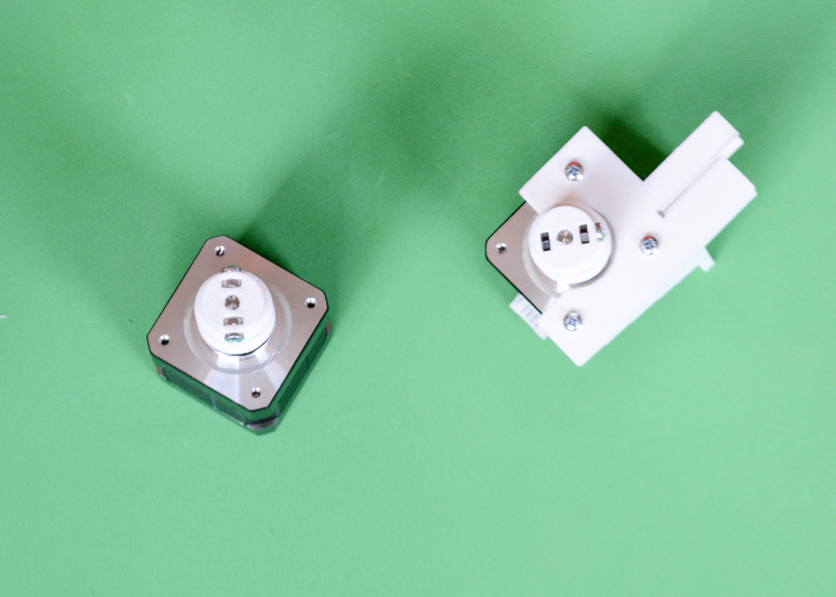
Now use the M3 6mm bolts to attach the motors to the H-BOT “corner pieces”
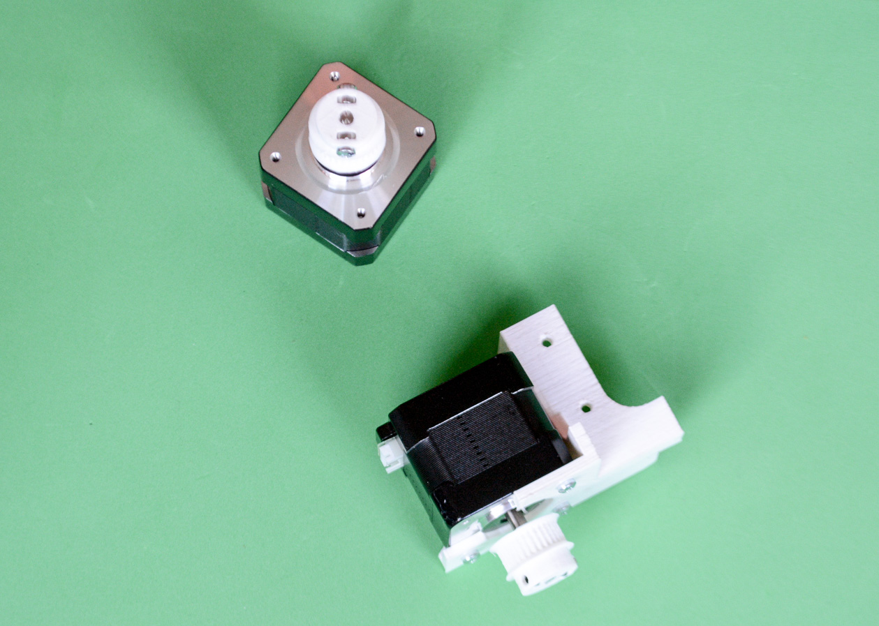
Pay attention to the motor´s connector orientation.
The ROBOT pusher: use 4xM3 6mm bolts and 4x M3 nuts to fix the two parts.
As all the Air hockey tables are slightly different you might need to adjust the total height of this PUSHER. Later, when you will be checking the free movement of this pusher all over the playing field, the bottom side of the PUSHER could touch the air hockey playing surface. Avoid it adjusting the 6mm bolts screwing or unscrewing them.
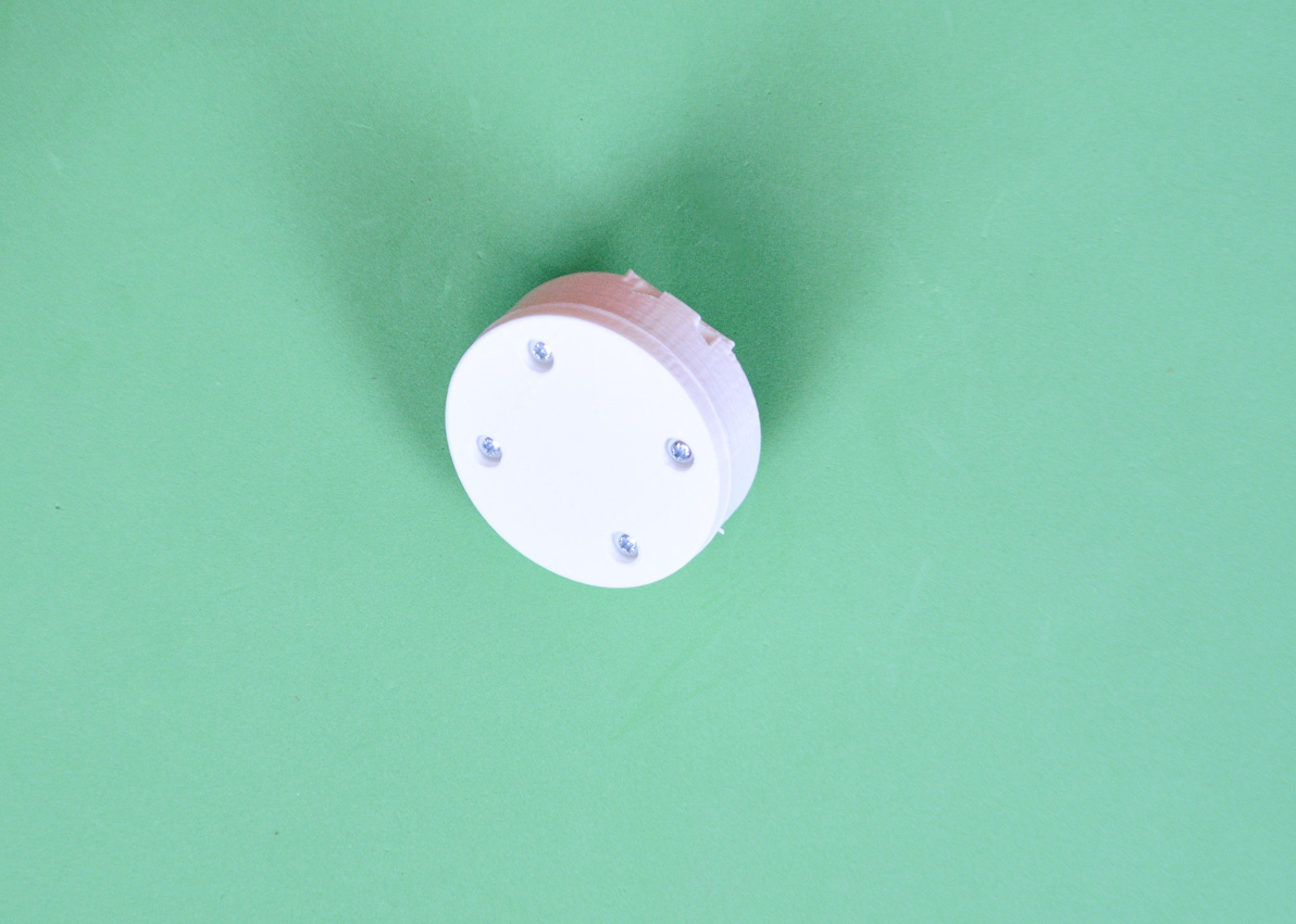
Done!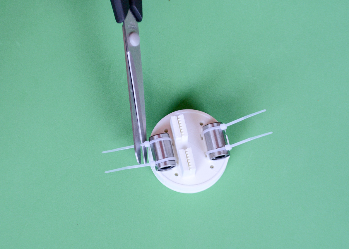
Now, fix two LMUU8 to the PUSHER using 4 zip ties. Do NOT tighten it up completely. Leave it a little bit loose until you run the aluminium tubes through the linear bearing later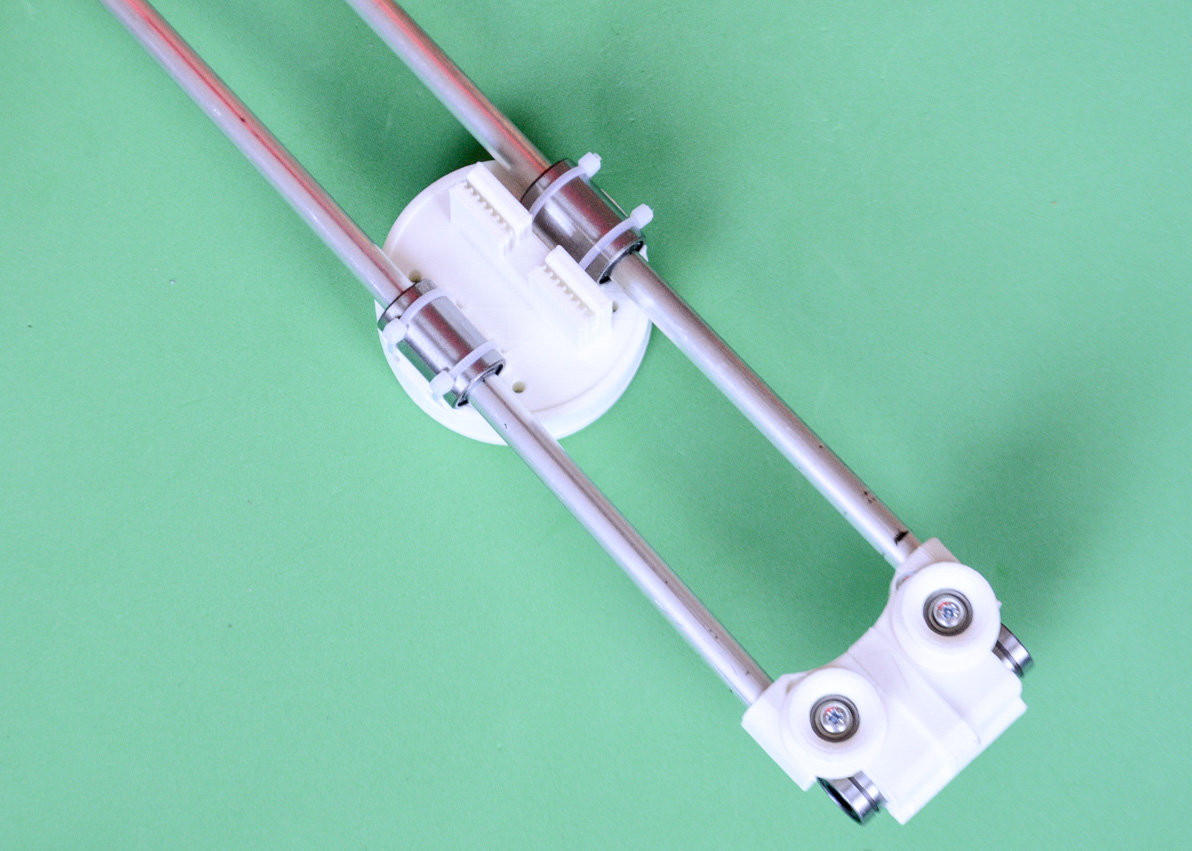
Run the aluminium tube through the PUSHER and attach the lateral SLIDER. Now you can tighten the LMU88U to the PUSHER. 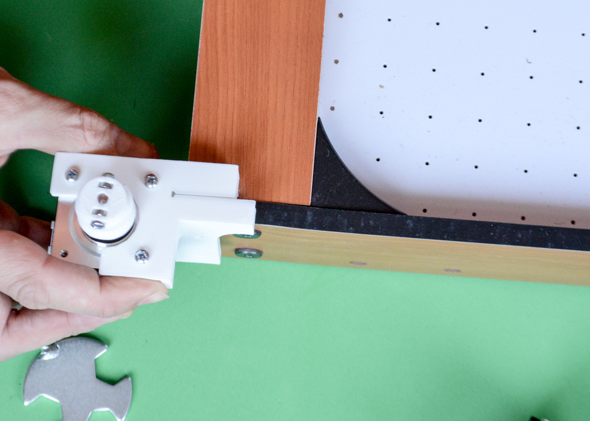
Attach the motors to the corners of the Air Hockey table using 2x Wood screws
Do not completely fix the H-BOT to the Air hockey table screwing all the screws yet. As the table might not be completely parallel to the H-bot structure you may need to leave some screws a little bit loose (just a little bit!).
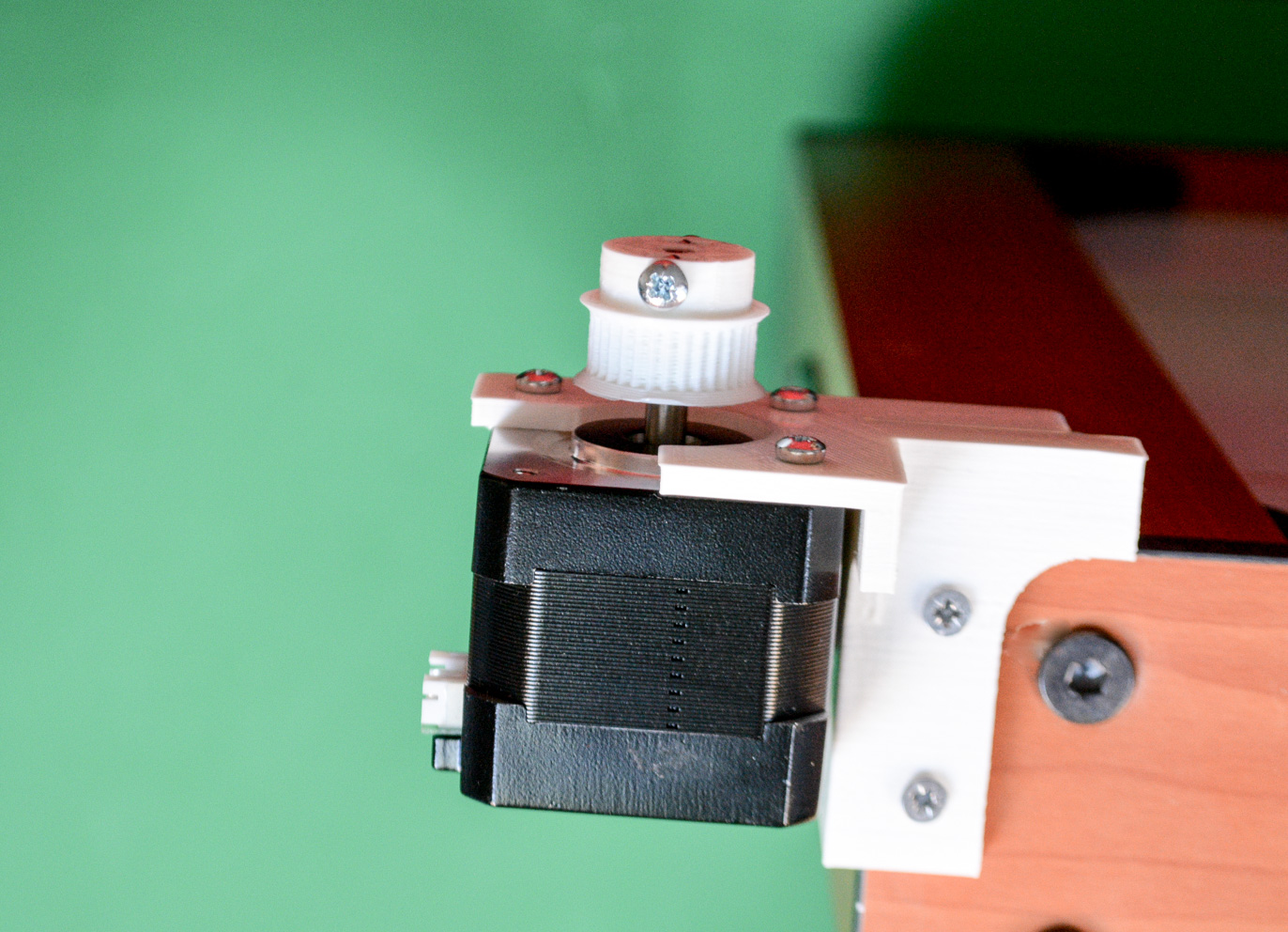
Side view of the motor and its support with the two screws.
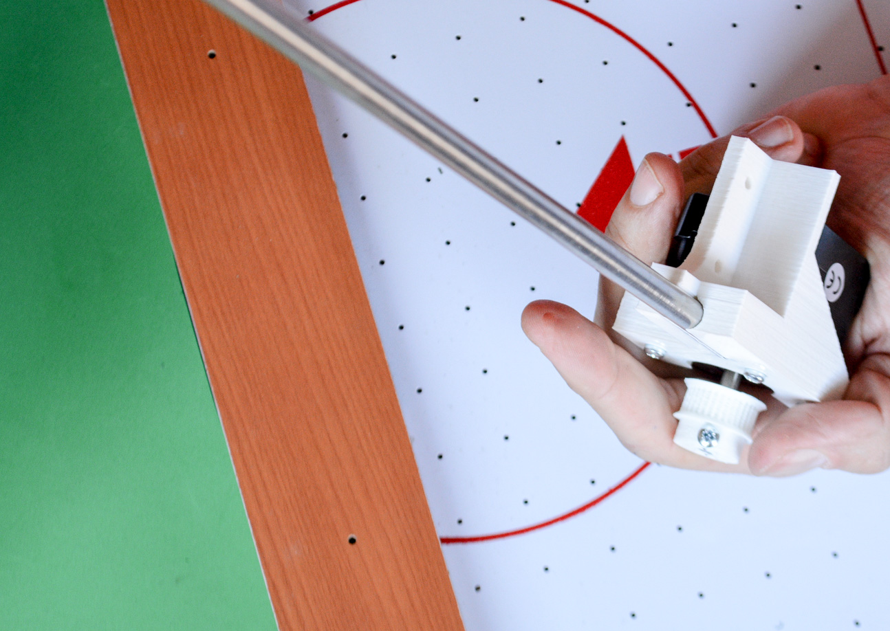
Steel round bar: you can push it into the channel after fixing the motor support to the Air hockey or before (as shown in the photo below). If you feel resistance, dismount the motor support and do it using a small hammer.
Place 2x LMUU8 in each steel bar as indicated above.
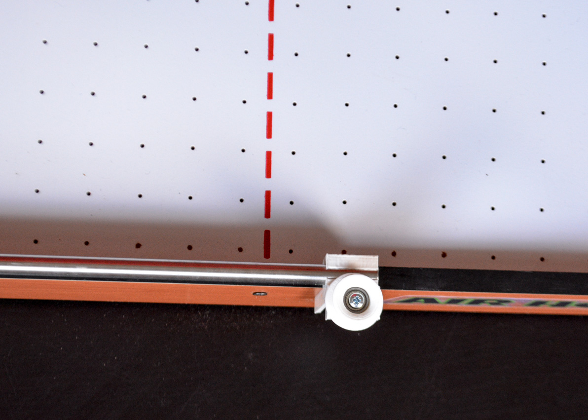
Use 2x Wood screws to fix the lateral support to the air hockey table.
Follow the above diagram to know where everything goes (Use 15mm M3 bolts).
Nice! It is time to attach the ROBOT ARM to the H-BOT. The lateral plastic parts will fit into the LMU88 with a CLICK! when placed correctly.
Check the video below. You should have NO RESISTANCE (at all) to the free movement of the Robot
If you feel friction:
- Check if the LMU88s in the LATERAL SLIDERS are aligned.
- Loose a little the zip ties of the robot PUSHER
- Are the steel bars aligned to the laterals of the Air hockey table? If not: loose a little the wood screws that are fixing the lateral support and motor support to the table.
H-BOT READY!

AIR HOCKEY ROBOT VISION SYSTEM
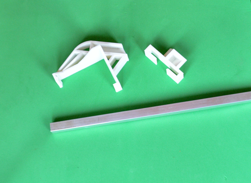
Let´s start with the support of the PS3 camera: pick the aluminium square tube and the two pieces shown above.
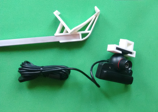
Attach the PS3 camera to its support
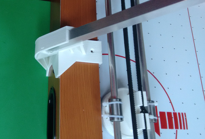
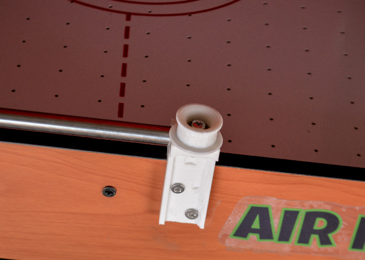
And fix the base to the air hockey table as indicated above. Start from the bottom side, the plastic part has a small wedge that will fit with the wooden back of the table. After fitting that wedge, fit the top. Use a wood screw at your discretion. The support base has to be placed close to the GOAL hole (can be shifted as long as you do not use the wood screw).
Another point of view of the supporting pole.
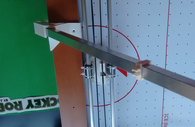
TOP VIEW: The camera centred over the middle of the playing field. The pole has two cable holders. Use them to keep the camera´s cable away of the field of view
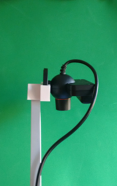
SIDE VIEW OF THE TOP OF THE POLE
CREATING THE COLOUR FEATURES (THINGS TO BE DETECTED BY THE ROBOT)
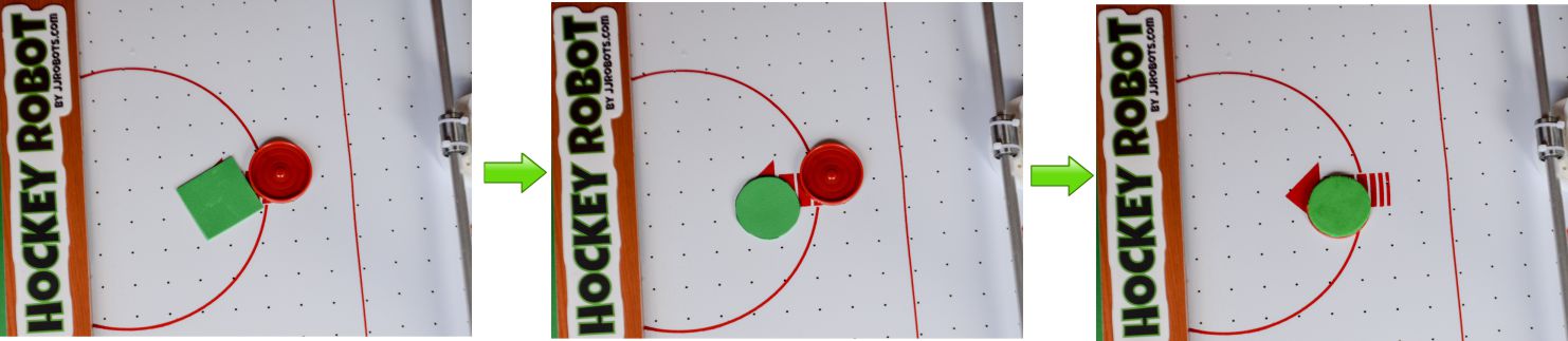
Cut the GREEN EVA foam with the shape of the PUCK (use it to draw its shape on the foam). Stick it to the PUCK using the double side tape
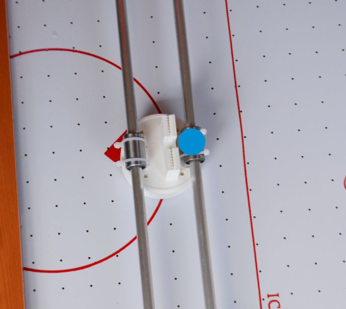
Cut a 20mm diameter circle of BLUE FOAM and place it as above. Use the double side tape to stick it.
NOTE: You can change the colours selected to identify both the Robot PUSHER and the PUCK. We have selected BLUE and GREEN as they are not present anywhere else. The Air Hockey Robot CODE (OPEN SOURCE robot) can be modified in order to work with any colour change picked by you.
Why using FOAM and not a 3D printed part or…a sticker? Due to the FOAM anti-reflexion capacity. Keep in mind that the ROBOT VISION SYSTEM can be tricked by FAKE reflections on a plastic surface. The ROBOT is not just detecting a colour but two features: SIZE AND COLOUR. (All these parameters can be modified in the CODE)
ADJUSTING THE PS3 CAMERA
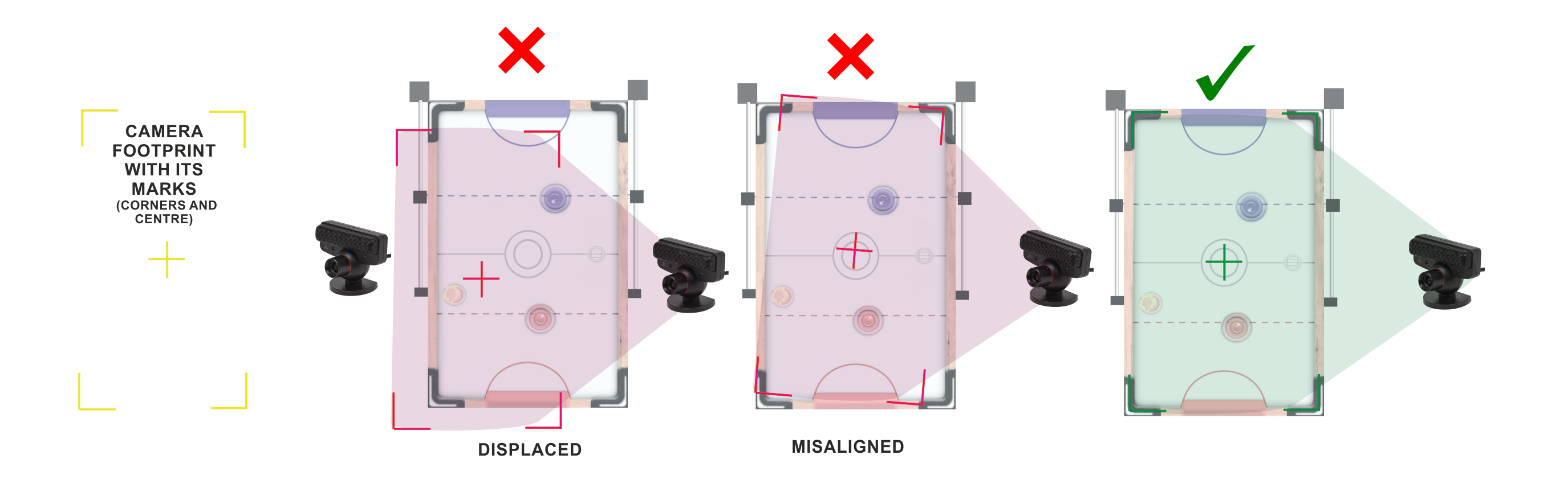
The camera will determine the playing field. There is a video below explaining some things, but basically: the PS3 camera, connected to the PC (use these Playstation 3 CAMERA DRIVERS if your computer can not recognise the camera) using a preset LAYOUT will create a VIRTUAL playing field limited by YELLOW MARKs. Everything outside this playing field layout will not be detected.
The computer will calculate (predict) the rebound of the PUCK on the “virtual” sides of this playing field and behave accordingly . This means: If the camera is not orientated correctly , the robot will misbehave due to a wrong PUCK trajectory prediction.
DOWNLOAD: AIR HOCKEY ROBOT VISION DETECTION SOFTWARE
Inside the above ZIP file, you will find:
1) DLL libraries needed to run the main executable (AHR_EVO.exe)
2) config.txt: a CONFIGURATION FILE. More info here.
3) log.txt : a file that will help you to know what the robot did (just in case…)
4) CheckHSV_image.exe: This executable will help you to get the HSV parameters of any object within the CAMERA field of view.
Helpful if you want to use another colours to detect both ROBOT and PUCK
5) The MAIN executable, in charge of detecting everything: AHR_EVO.exe
Ok. Next STEPS:
- Download the VISION DETECTION SOFTWARE
- Extract the files
- Connect the PS3 camera to your PC (check if it is properly recognised by the computer. Drivers here)
- Run the AHR2.exe (if you have a webcam connected, you might need to disconnect/disable it temporally. Otherwise, the AHR2,exe could use it instead the PS3 camera). A window will pop-up showing something similar to the video displayed below.
- Rotate, move, twist the PS3 camera until the image is centred as indicated in the video below: The YELLOW MARKS have to be placed over the corners of the Air hockey table. As explained before, those marks will create the “virtual” playing field. Both the ROBOT and the PUCK should be detected by now.
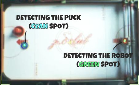
- The ROBOT and the PUCK are being detected in this screen capture. This CAMERA window will place a CYAN and GREEN spots over both features
.
An uniform illumination is extremely important for the vision system. Avoid shadows, reflections (and if you can, fluorescent lighting).

HARDWARE:CONNECTING EVERYTHING
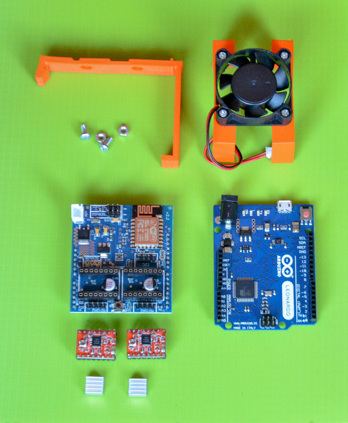
Above. Elements needed to control the Robot: jjRobots Brain Shield, Arduino Leonardo, 2x Stepper motor drivers (+heatsinks), FAN (12v) and 3D parts support + bolts/nuts
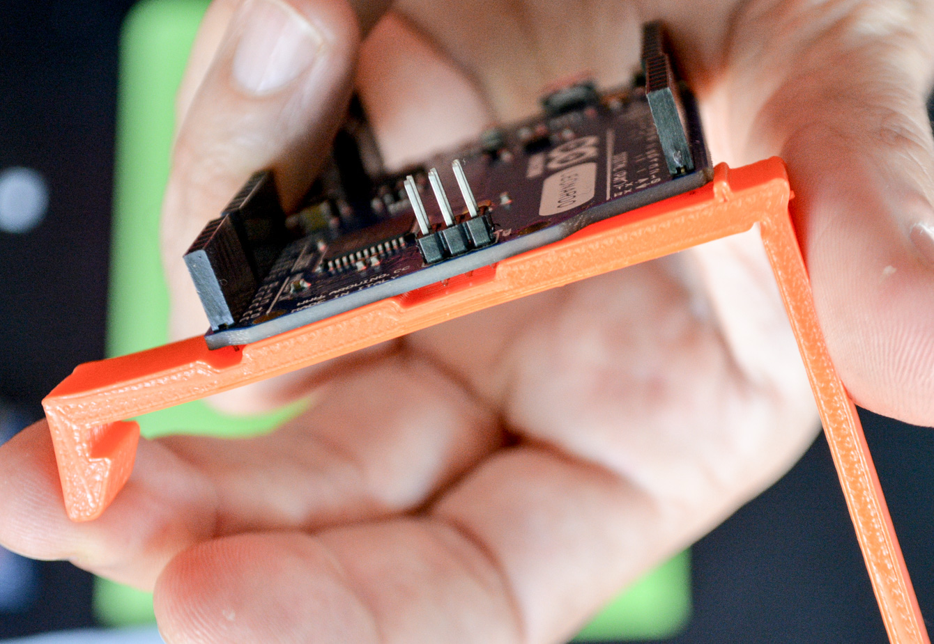
Fix the Arduino Leonardo to the 3D printed part indicated above. Use 2x 6mm M3 bolts + nuts to do that.
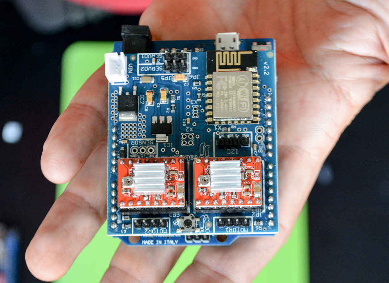
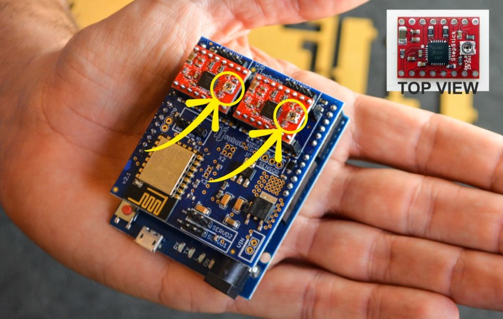
Above: place the stepper motor drivers as indicated above. Pay attention to their orientation. Connect both Arduino Leonardo and the jjRobots Brain Shield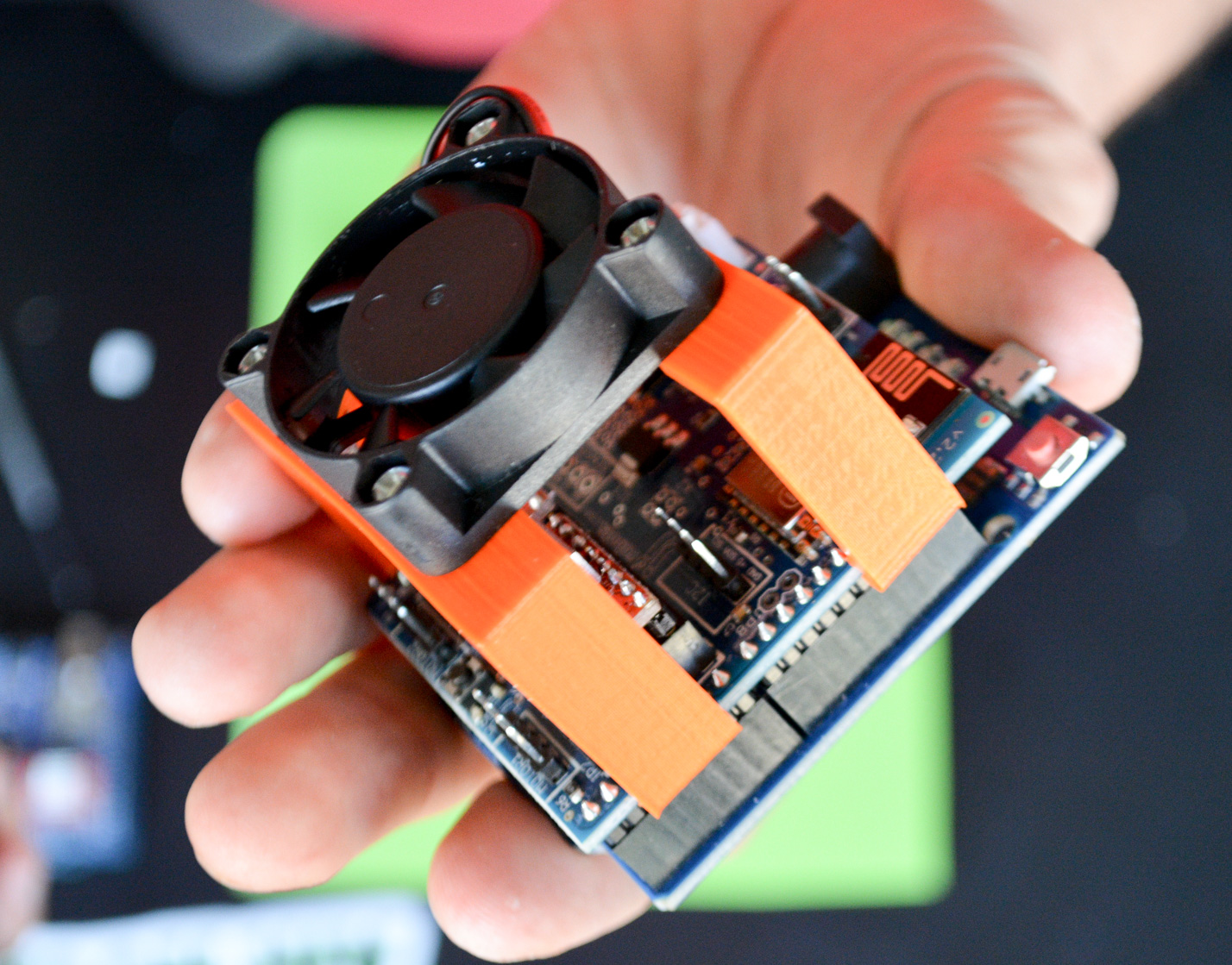
Fix the FAN to the two legs using 4x 6mm M3 bolts + 4xM3 nuts. The legs will be bracing the Brain Shield from the sides. Centre the FAN as shown above.
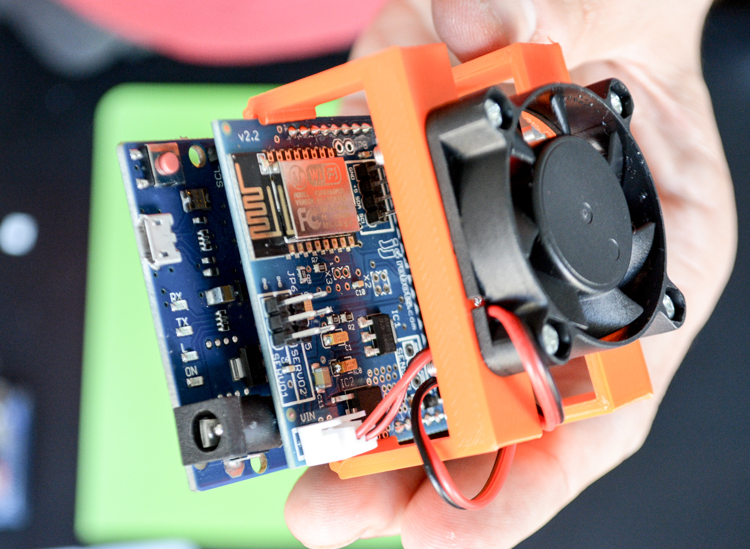
Connect the FAN to the VIN output of the jjRobots BRAIN SHIELD. There is only one way to connect it, but just in case, take a look to the electrical diagram below.
Above: Side view of the Brain Shield + ancillary elements already plugged.
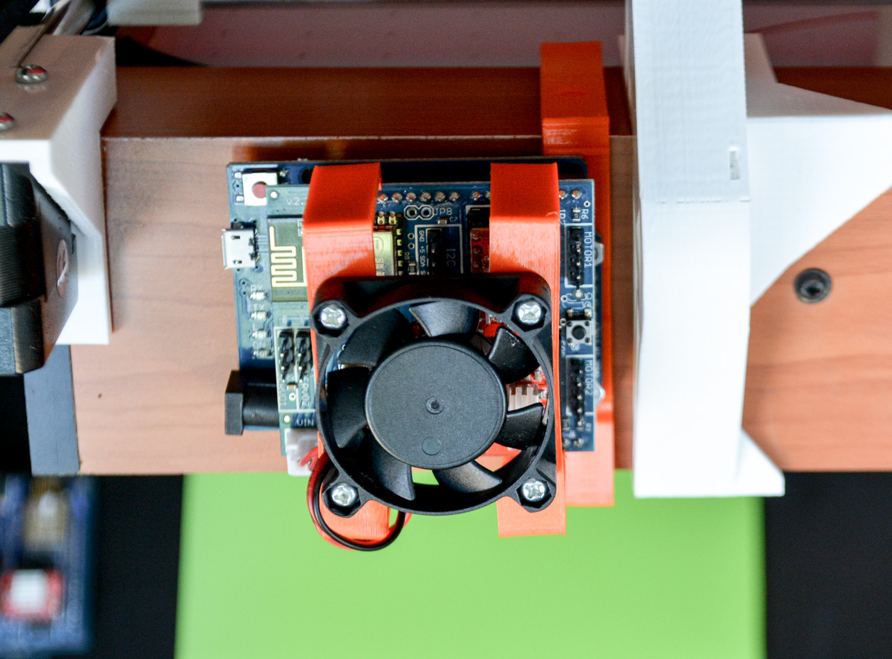
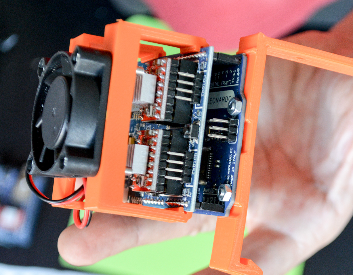
TOP VIEW of the Electronics attached to the Air hockey Table. NOTE: if you want to fix it permanently to the Air hockey table, use a wood screw in the hole hole (you will see it on the top side of the support 3D part)
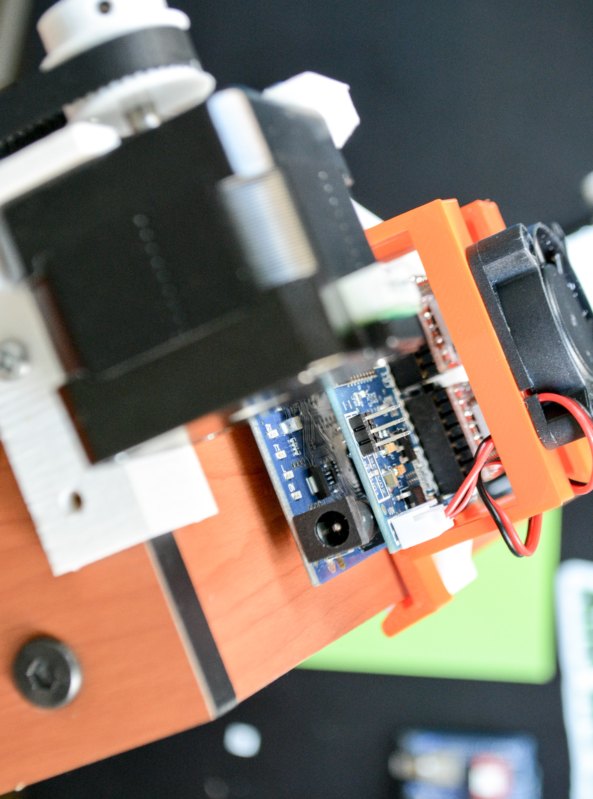
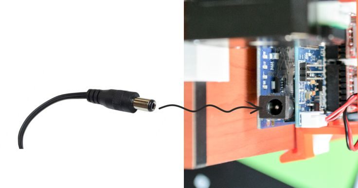
SIDE VIEW: POWER CONNECTOR where you will plug in the power supply jack.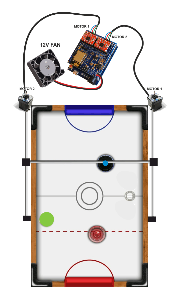 Above: How to connect all the cables. DOUBLE CHECK THE POLARITIES! The stepper motors can handle an inverted polarity but the FAN can not say the same.
Always, always keep the FAN blowing while the Air Hockey Robot is working. The stepper motor drivers might get damaged is there is not a constant air flow cooling them down

ASSEMBLING THE AIR HOCKEY TABLE LEGS
Use the bolts provided with the AIR HOCKEY TABLE to attach the four LEGs to the TABLE
OPTIONAL (BUT RECOMMENDED)
In the AIR HOCKEY ROBOT KIT, there are two small plastic wedges (see photo below). They are a sort of “gaming help/assistance”. Intended to send back to the middle of the field the PUCK when it gets stuck behind the robot or next to the corners. They will lift a little the air hockey table in the robot side. Raising the table on that side will prevent someone to put the fingers in the robot “dominions” trying to move the PUCK if it stops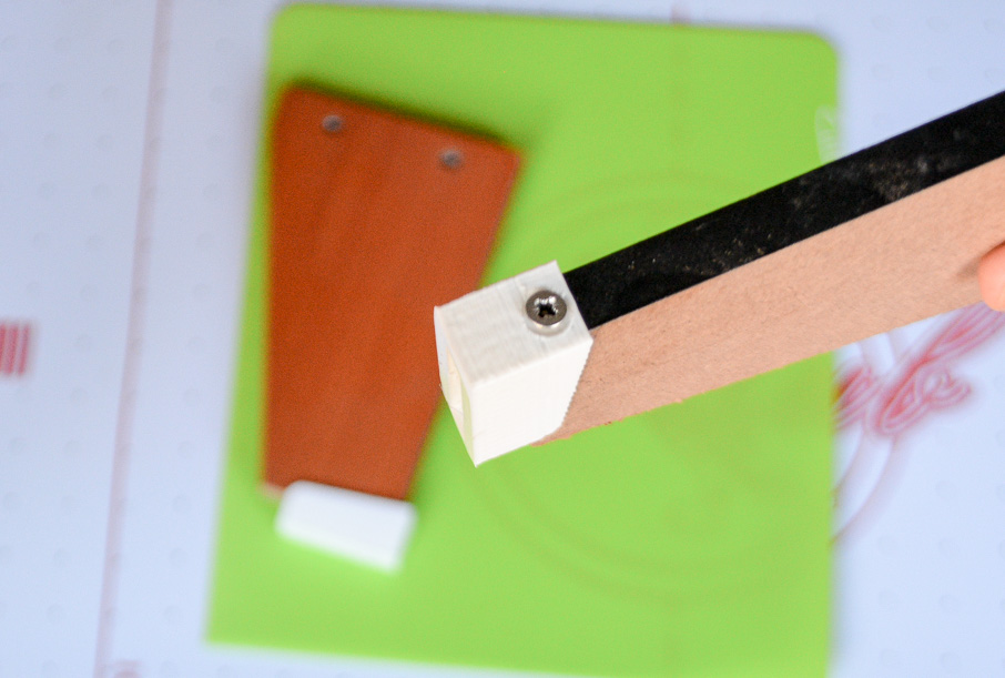
PROGRAMMING THE ARDUINO LEONARDO
STEPS:
- Download the ARDUINO CODE from HERE (or go to jjRobots GITHUB REPOSITORY and download it from there) ahrobot_evo
- Connect the USB cable provided to the Arduino LEONARDO
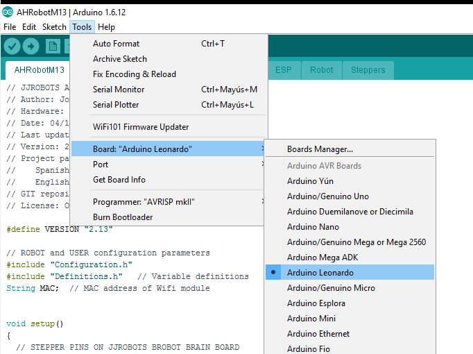
- Compile the CODE using the ARDUINO IDE (The CODE is compiling and has been tested under ARDUINO IDE 1.6.12) and upload it (Below:You have to select the ARDUINO LEONARDO board and its PORT in the “TOOLS” MENU)
CHECKING THE ROBOT H-BOT AND MOTORS
Well, it is time to check the Robot movement skills. The jjRobots Brain Shield has a button placed between the motors connectors: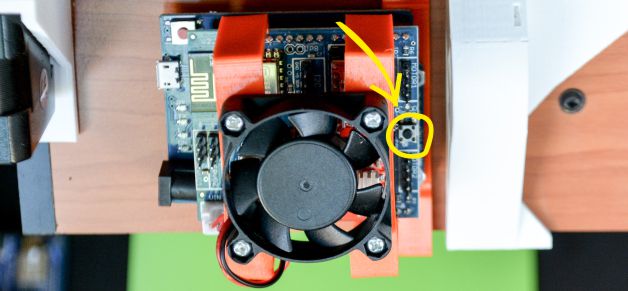
Push it if you want the robot to make a MOVEMENT TEST PATTERN . This will let you know if everything is fine with the structure and motor control. This is the first time you will see how the robot moves by itself, so do not place anything on the air hockey table and be careful with your fingers! Play the video below to be prepared for what it is coming 🙂
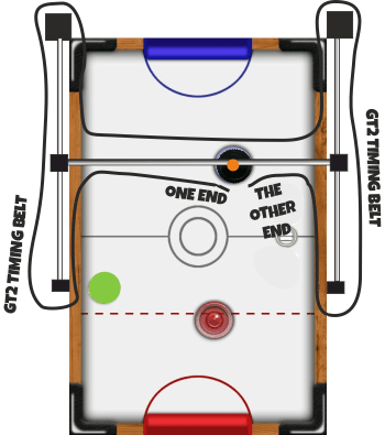
BEFORE TURNING IT ON: PLACE THE TIMING BELT IN THE H-BOT STRUCTURE
If your robot is not making the pattern shown in the video, read below and find your problem:
- The robot is crashing against one side of the air hockey table: check the polarity of the motor cables.
- I am hearing a cracking noise coming from the motor/s and the robot does not move at all or not enough to draw the pattern: the stepper motors can not move the robot due to lack of power. This can be caused by:
- There is too much friction in the H-bot structure: Check everything again. Is the timing belt too tight?
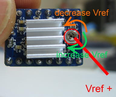
- Try to adjust the STEPPER MOTOR DRIVERS output current via its potentiometer
The Air Hockey robot uses two powerful stepper motors. Keep an eye on where you place your fingers!.
Sudden accelerations of the robot within its playing area could catch you unaware. Before adjusting anything remember to disconnect its power supply.
HARDWARE + SOFTWARE : FINAL CHECKS
So far, you have:
- Checked the VISION SYSTEM.
- Checked the H-BOT structure and how the robot makes the initial movements without issues.
Now it is time to check everything working together:
- Connect the 12V POWER SUPPLY to the ARDUINO LEONARDO and let the robot make the initial movements (Just in case: have you checked the FAN is working?)
- Connect your computer to the “JJROBOTS_XX” WIFI NETWORK using the password: 87654321
- Run the VISION SYSTEM EXECUTABLE (AHR_EVO.exe). From now on, the APP will be in charge of controlling the ROBOT according to the info sent in real time from the VISION SYSTEM. The CONTROL commands are constantly sent via UDP packets to the jjRobots Brain Shield. In the same way, the info with the current position and trajectory of the PUCK and ROBOT is sent back to the computer
- Check the ROBOT´s response to visual “stimulus”. Watch the video below:
5. If everything went fine, feel free to turn ON the AIR HOCKEY TABLE FAN (the switch is under the table)
6. Enjoy!
FINALLY, TAKE A LOOK TO THIS LAST VIDEO.
IT SHOWS AN AIR HOCKEY ROBOT IN WORKING CONDITION.
TROUBLESHOOTING
MY robot is not making the pattern shown in the video after turning it ON:
- The robot is crashing against one side of the air hockey table: check the polarity of the motor cables.
- I am hearing a cracking noise coming from the motor/s and the robot does not move at all or not enough to draw the pattern: the stepper motors can not move the robot due to lack of power. This can be caused by:
- There is too much friction in the H-bot structure: Check everything again. Is the timing belt too tight?
- Try to adjust the A4988 STEPPER MOTOR DRIVERS output current via its potentiometer:
LINKS:


AIR HOCKEY ROBOT ORIGINAL