Know more about the VISION SYSTEM
Run the AHR_EVO.exe application (this file can be found within the VISION SYSTEM zip file). If you have already installed the PS3 camera drivers, you will see something like this:
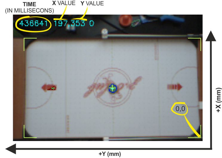
The values on the top left corner represent: TIME (in milliseconds) since the APP started, X VALUE (position of the CENTRE of the detected PUCK) and Y VALUE (position of the CENTRE of the detected PUCK). The ROBOT coordinate system ORIGIN is located on the BOTTOM RIGHT from our current point of view. This means that if you place the PUCK in the middle of the AIR HOCKEY TABLE you will get a X and Y equal to the PHYSICAL CENTRE of the REAL AIR HOCKEY TABLE (half of the real height and width of the table). All the measurements are in MILLIMETRES
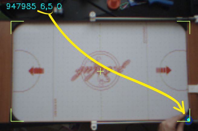
So, if you place the PUCK in a CORNER, you will get or a ZERO,ZERO (or almost) or the TOTAL length and /or width of the table:
But, how does the ROBOT knows the relation between a PIXEL and a MILLIMETRE?
We will talk about that below. But the short version is: inside the CONFIG.TXT file there is a parameter that define that relation.
How can I modify the VISION SYSTEM DEFAULT PARAMETERS?
Inside the VISION SYSTEM FILES.zip, you will find a .txt file named CONFIG.TXT. This is the AIR HOCKEY ROBOT VISION SYSTEM CONFIGURATION FILE. If you open it (e.g. with the Notepad app), this is what you will see:
# AHR_EVO configuration file
CAMERA 1 # 0=FIRST CAMERA, 1=SECOND CAMERA, -1=OPEN input.mpeg video
PROTOCOL UDP
CAMPIXTOMM 1.25 # THIS DEPENDS ON YOUR CAMERA POSITION
TABLELENGTH 710 # TABLE SIZE IN mm
TABLEWIDTH 400 # TABLE SIZE IN mm
PUCKMINH 80 # PUCK HSV DETECTION PARAMETERS
PUCKMAXH 126
PUCKMINS 35
PUCKMAXS 155
PUCKMINV 50
PUCKMAXV 190
ROBOTMINH 136 # ROBOT HSV DETECTION PARAMETERS
ROBOTMAXH 172
ROBOTMINS 126
ROBOTMAXS 217
ROBOTMINV 67
ROBOTMAXV 162
ROBOTYOFFSET 15  # Robot offset from robot mark (projected to table) to robot puck center
FPS 60
VIDEOOUTPUT YES # YES or NO
LOG YES # YES or NO
PREVIEW YES # YES or NO or RAW
What do all those parameters do?
CAMERA 1 # 0=FIRST CAMERA, 1=SECOND CAMERA, -1=OPEN input.mpeg video
If you have several cameras connected to your PC (for example, there is webcam already connected and you want to use it at the same time you are playing with the Air Hockey Robot), changing the numerical value from 0 to 1 the AHR_EVO.exe application will pick one or the other. By default : CAMERA 1 (we already have a webcam connected to the computer)
PROTOCOL UDP
The protocol used to send the data from the COMPUTER to the jjRobots Brain Shield. More info about the UDP protocol here.
CAMPIXTOMM 1.25 # THIS DEPENDS ON YOUR CAMERA POSITION
This is the relation between a PIXEL and a MILLIMETRE: The robot needs to know the REAL distances in order to make decisions.If you are not placing the camera in the right position or if you are modified its location on purpose you will need to modify this value.
TABLELENGTH 710 # TABLE SIZE IN mm
TABLEWIDTH 400 # TABLE SIZE IN mm
They define the length and width of the PLAYING COURT (not the TOTAL dimension of the AIR HOCKEY TABLE just the playing court)
PUCKMINH 66 # PUCK HSV DETECTION (6 PARAMETERS)
PUCKMAXH 94
PUCKMINS 55
PUCKMAXS 155
PUCKMINV 56
PUCKMAXV 185
ROBOTMINH 6 # ROBOT HSV DETECTION PARAMETERS (6 PARAMETERS)
ROBOTMAXH 22
ROBOTMINS 95
ROBOTMAXS 180
ROBOTMINV 90
ROBOTMAXV 200
Parameters that define the HSV features of the elements to be detected on the PLAYING COURT (PUCK and ROBOT in this case). 6 parameters define a COLOUR in the HSV COLOUR SPACE: Hue (min and max), Saturation (min and max), and Value (min and max)
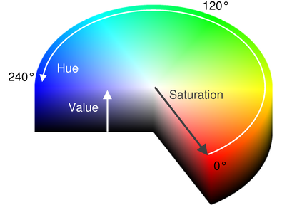
How can I know the equivalent colour in the HSV space?
Use this online COLOUR PICKER App to know it
I would like to recognise other features/
colours with the VISION SYSTEM. Or adjusting the recognition parameters. How?
If you want to change the default colour to be detected by the robot VISION SYSTEM, you just have to change the values according to their new HSV parameters.
To make things easier, we have created and included an executable inside the VISION SYSTEM zip files, the CheckHSV_image.exe
Start this APP and play with its SLIDER CONTROLS (see image below) until your new selected colour is perfectly delimited over the BLACK Background:
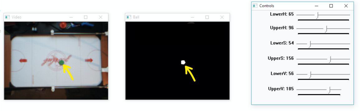
Notice how we have set the 6 HSV parameters values (above, on the right) in the “CONTROLS” window in order to only see the SHAPE of the GREEN PUCK and nothing else on the PLAYING COURT:
PUCKMINH 65 # PUCK HSV DETECTION (6 PARAMETERS)
PUCKMAXH 94
PUCKMINS 54
PUCKMAXS 156
PUCKMINV 56
PUCKMAXV 185
But, why are there TWO values for H,S and V (MIN and MAX)?
We want the robot to be able to detect the colour we have picked with certain tolerance.
For example, the REAL GREEN (shown above) HSV values of the PUCK could be 84,100 and 90, but under certain lighting conditions the CAMERA might detect another slightly different values. That is the reason we need to create a “detecting threshold”, to allow the Robot to properly determine the location of the elements on the playing field.
ROBOTYOFFSET 15 # Robot offset from robot mark (projected to table) to robot puck center
The Robot needs to know how far the centre of the COLOURED FOAM CIRCLE is from the CENTRE of the PUSHER. This value represent that distance
FPS 60
You can CAP the maximum FPS (frames per second) delivered by the CAMERA (just in case you want to try things). By default : YES
VIDEOOUTPUT YES # YES or NO
Do you want to RECORD the VIDEO in real time ? By default : YES. Video name: output.mpeg, located in the same folder where the AHR2.exe is.
LOG YES # YES or NO
Do you want to store a LOG FILE with all the parameters detected (into the “log.txt” file) in real time? By default : YES. Parameters stored: Configuration parameters, location of the PUCK
PREVIEW YES # YES or NO or RAW
Do you want to see the PREVIEW VIDEO in real time on your computer´s screen? By default : YES
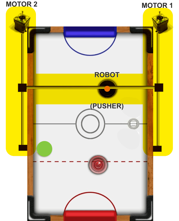
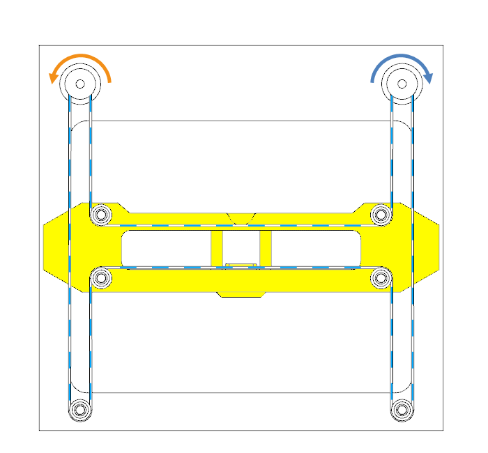
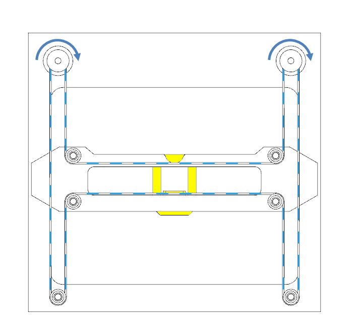
Tell me about the Air Hockey Robot EVO structure. How does it work?
The H-bot structure allows the Air Hockey Robot EVO to move itself with only two motors.
The advantages: Both motors push all pull at the same time, sharing the load to move. It is straighforward and clean. It is fast and fully detachable
The cons: uneven forces. We have solved it reducing to the max the friction among elements and the mass to move using aluminium tubes (not bars),
Take a look to Air Hockey Robot EVO H-Bot and to the animated images below to know how the robot moves using this H-bot system
This is a work in progress. The CODE has been thoroughly commented but we will add comments and tips here. Feel free to make the most of the Air Hockey Robot COMMUNITY if you have ideas or comments
VALUES: ACCELERATIONS/ SPEED
The Air Hockey Robot, as any real system, has its own limitations. High accelerations and top speed will make the motors to not be able to respond properly (missing steps). Feel free to play with the acceleration and speed values: the higher the acceleration value, the fastest the robot response, but that means: more Amperes will be requested to the power supply and to the stepper motor drivers. Access to these values in the configuration.h file (arduino code):
// ABSOLUTE MAX ROBOT SPEED AND ACCELERATION
// THIS VALUES DEPENDS ON YOUR ROBOT CONSTRUCTION (MOTORS, MECHANICS...)
// RECOMMENDED VALUES FOR 12V POWER SUPPLY
#define MAX_ACCEL 280 // Maximun motor acceleration in (steps/seg2)/1000. Max recommended value:280
#define MAX_SPEED 32750 // Maximun speed in steps/seg. Max absolute value: 32767!!

#define MIN_ACCEL 80
#define MIN_SPEED 5000
#define SCURVE_LOW_SPEED 2500
#define SCURVE_HIGH_SPEED 28000
NOTE: we will post more info and tips here about how to modify the robot´s CODE as we get comments/questions from you 😉