Below: Elements included in the KIT . All you need to create this robot (+3D printed parts)
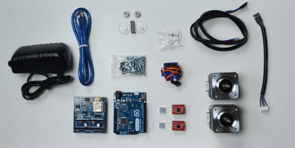
- 2x 623 bearing
- Threaded steel rod (3mmØ,80mm length) (not shown on the photo above)
- 1x compression spring (4,5mmØ, 10 mm length)
- 2x 1.8deg HIGH QUALITY NEMA 17 Stepper motors (40mm length) (4.4Kg/cm torque)
- Motor cables (14+70 cms long)
- USB cable (to program the Arduino)
- 1x SG90 servo
- Arduino Leonardo compatible
- B-robot Brain Shield
- 2x A4988 Stepper motor drivers
- Power supply 12v/2A
- 2x 6mm M3 bolts
- 14x 16mm M3 bolts
- 4x M3 nuts
- 2x 20mm Suction Cups (to keep the egg/sphere tight in place)
- 1x M3 wingnut
- 1x Sharpie pen
OTHERS:
- cable wrap (optional but makes everything look prettier..)
You can get the KIT in our SHOP or get the elements by yourself. If you like this robot and have in mind to assemble any other JJrobot (or all of them) , take a look to the MOST AWESOME ROBOTICS KITS! here
Back to the Sphere-O-Bot: Prior to start reading this Assembly guide, we are assuming you already have all the 3D parts printed (you can get the 3D models here) and the elements listed above.
READ THIS:
Below, we will show you the steps to follow. This is a quite simple process. Will take no more than an hour (or so). Pay attention to the cable polarities (check everything twice). If you have issues, refer to the COMMUNITY
STEPS:
-
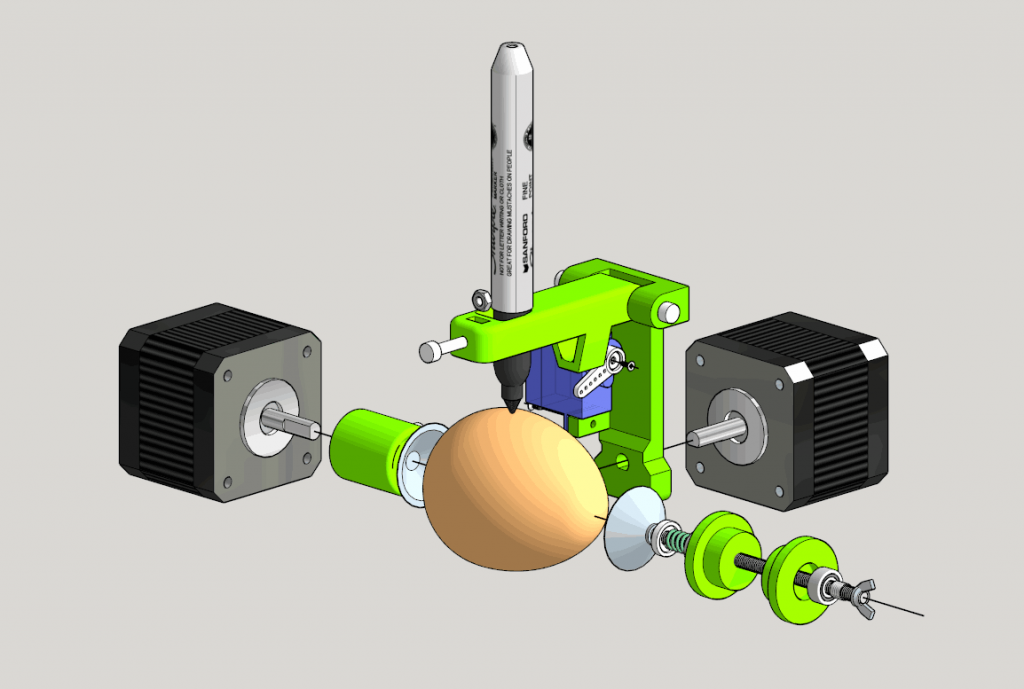
Take a look to the general diagram
This sphere bot has a painting arm (the structure holding the pen) drove by a stepper motor (the DRAWING stepper motor from now on). Another stepper motor is in charge of rotating the object to be painted (egg, sphere…). To keep the object in place we will use two suction cups: one attached to the EGG stepper motor, and the other on the other end. A small spring will push one suction cup into, in this case, an egg helping to hold it tight as we are painting on its surface. Because we will need to raise the pen as we are drawing on the surface, a SG90 servo will be used for this purpose. Please note that the main Sphere-O-bot frame has not been displayed in most of the images below.
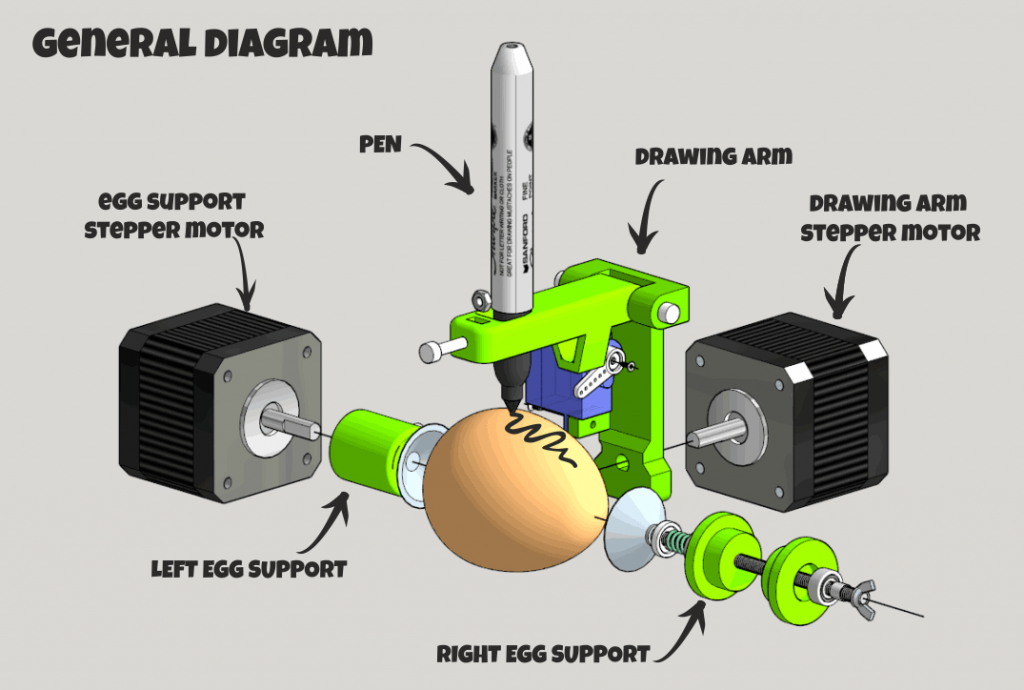
Assembly diagram
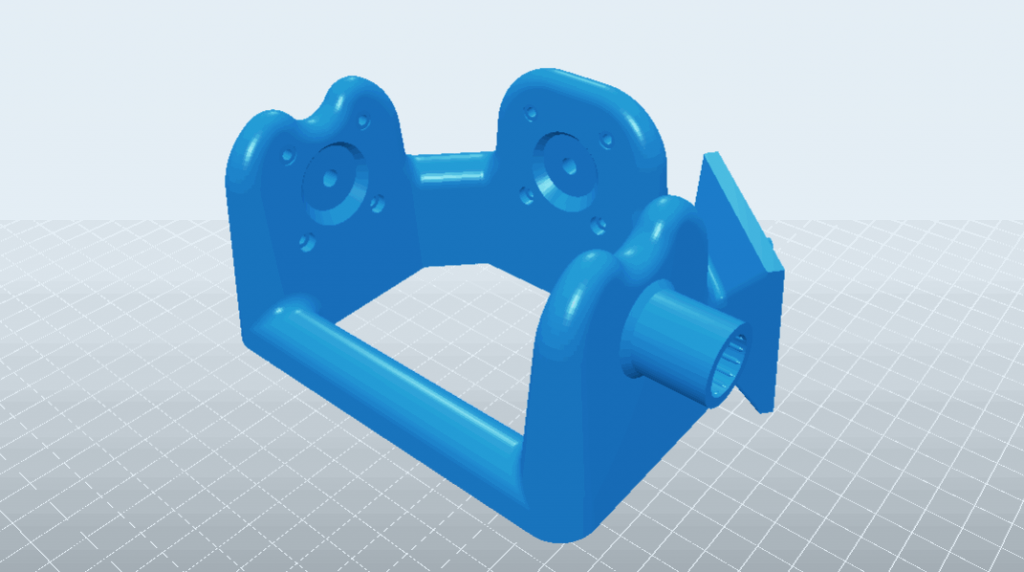
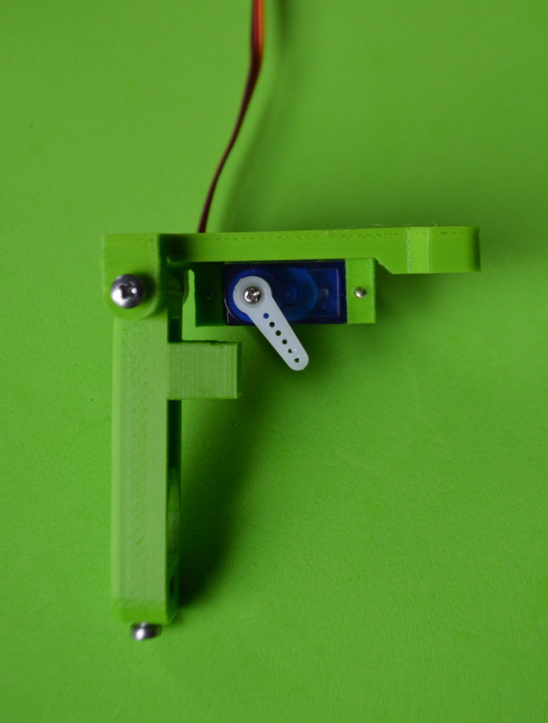
2. Let´s start with the drawing arm and the left egg support.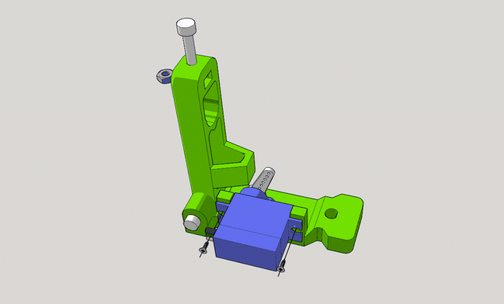
Fix the servo to the piece indicated in the image above. Use two servo´s screws to attach it to the 3D printed drawing arm.
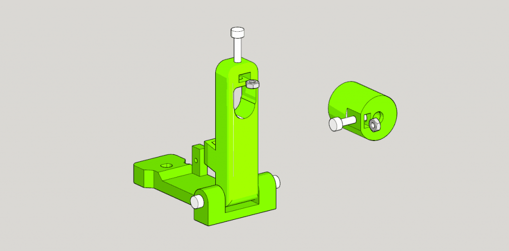
Put a M3 nut inside the hole prepared for it and screw one 16mm M3 bolt in it. Do the same for the Egg holder (right side of the image above). The hinge for this drawing ARM has been created using 2x 16mm M3 bolts. This hinge should be free to rotate after screwing these two bolts.
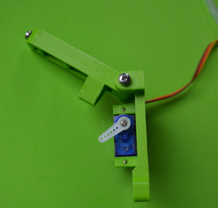
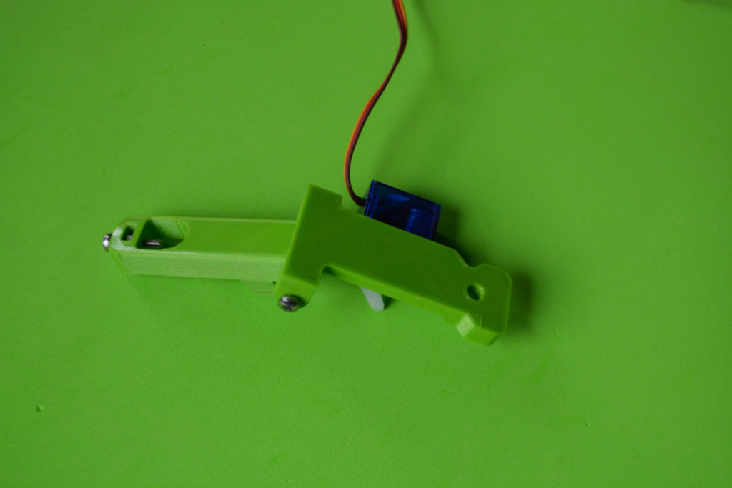
See below three photos of the arm already assembled.
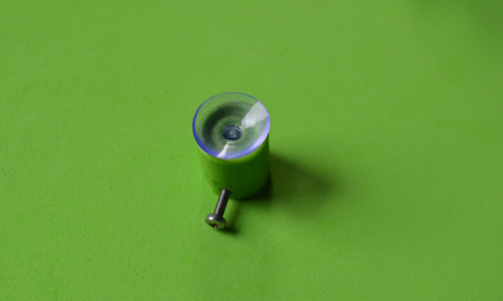
Push one of the suction cups inside the D shaped hole of the EGG SUPPORT as indicated below
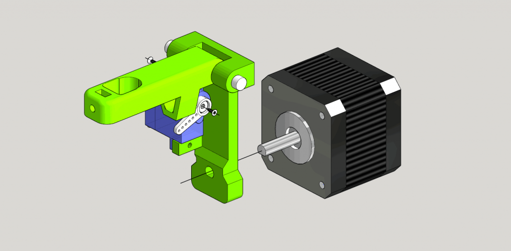
3. Fixing the stepper motors and assembling the X axis rod
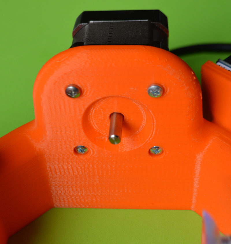
Fix both stepper motors to the MAIN FRAME using 8x 16mm M3 bolts. Quite straightforward
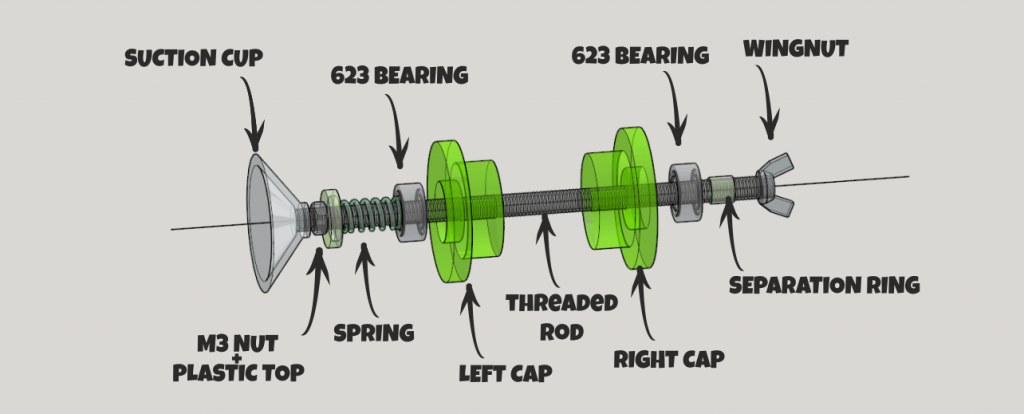
Above: the assembly diagram of the X axis threaded rod (80 mm long, M3). Place all the elements as is shown in the image above. The correct order:
- Suction cup
- M3 nut
- 3D printed TOP piece
- Spring
- 623 bearing (it has to be embedded into the LEFT CAP)
- LEFT CAP piece
- IMPORTANT: HERE GOES, IN THE MIDDLE, THE MAIN FRAME: BETWEEN THE SIDE CAPS. THE MAIN FRAME HAS NOT BEEN DISPLAYED IN THIS IMAGE.
- RIGHT CAP piece
- Tiny separator RING (3D printed part)
- WINGNUT (M3)
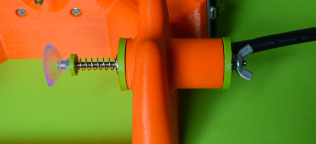
Finished! The side CAPS have to be firmly embedded into the main frame
4. Placing everything in the right place
Above:Push the assembled DRAWING ARM into the DRAWING Stepper motor´s axis. Be gentle but push it firmly. 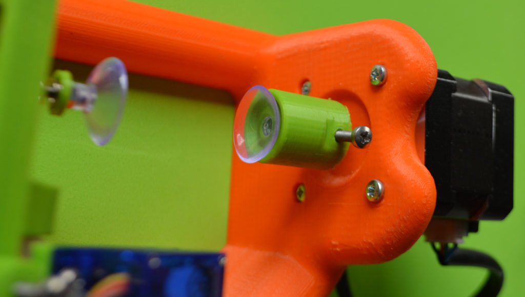
Fit the LEFT EGG support into the EGG Stepper motor´s axis
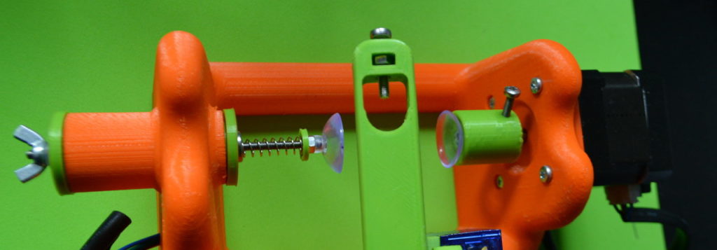
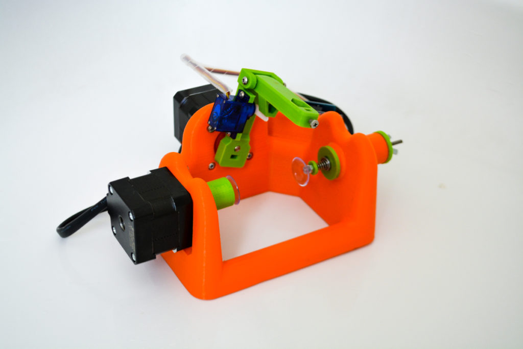
Above: this should be the top view of your Sphere-O-Bot by now.
Double check, paying attention to the diagram above, that you have set everything fine. The pen and the egg are used in this photo as a reference (you do not need to place them now).
NOTE: The servo´s ARM will need some adjustments. This arms is in charge of lifting the DRAWING ARM as the robot paint. You will need to re-set its angle during the calibration process (It´s easy)
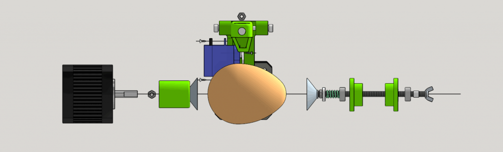
Above. General diagram. FRONT VIEW. Again: the main frame is not displayed. Is this like you robot?
5. Electronics + Cables. How to connect everything.
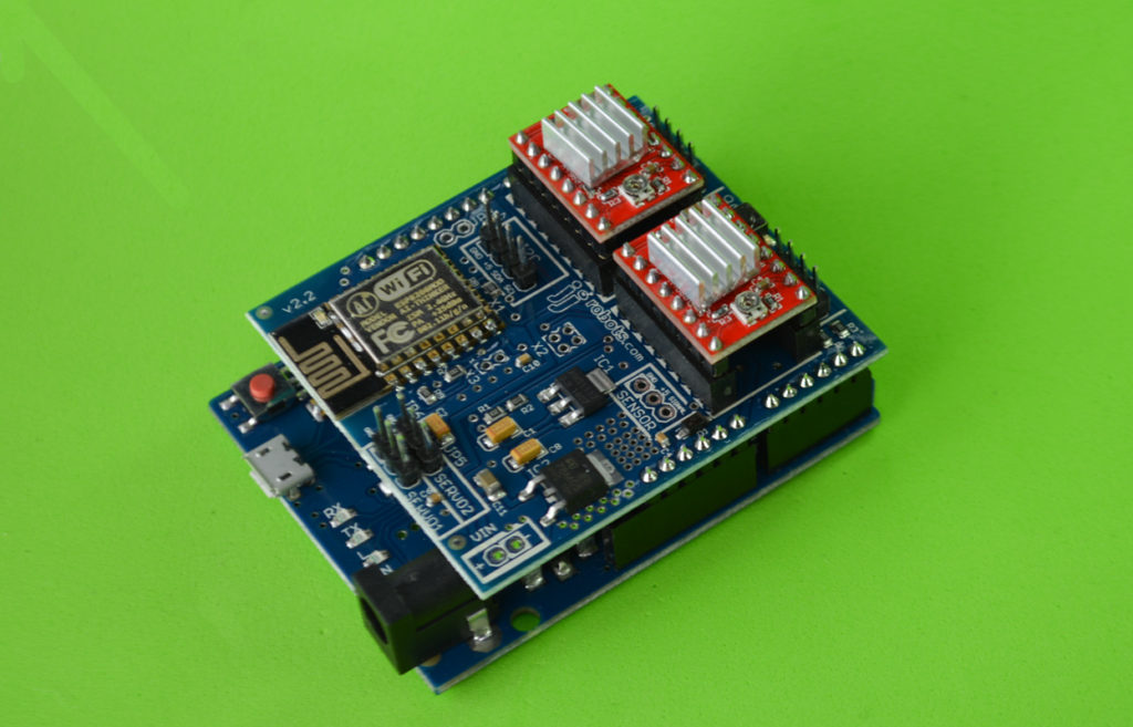
Well, we are almost there. Pick the JJrobots Brain Shield, the Arduino Leonardo and the 2x stepper motor drivers. Connect everything as below. Check the orientation of the stepper motor drivers (red modules) twice.
Fix the electronics to the back side of the Sphere-O-bot MAIN FRAME using M3 6mm bolts (2 are enough).
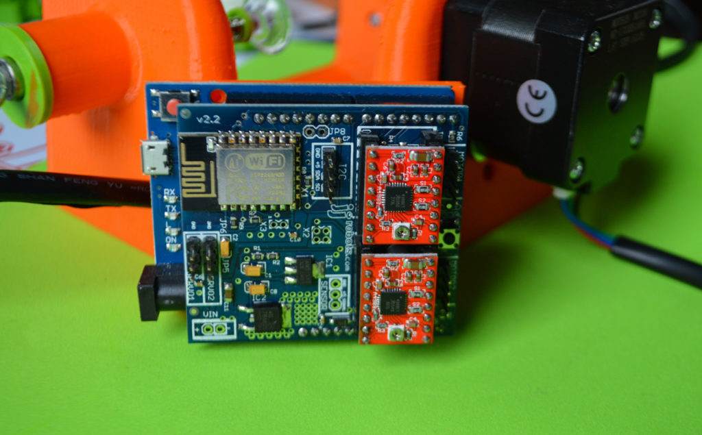
Below: TOP VIEW of the electronics already attached to the frame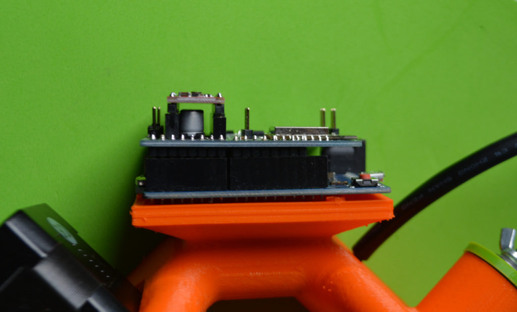
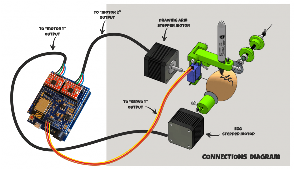
Above: connect the cables as indicated. Check the polarities TWICE!
6. PROGRAMMING THE ARDUINO LEONARDO
Program the Arduino leonardo using the ARDUINO IDE (v 1.8.1) software. It is quite simple:
1) Download the ARDUINO IDE (v 1.8.1) here: https://www.arduino.cc/en/Main/Software and install it.
2) Run the software. Select the Arduino Leonardo board and the proper COM PORT (should be COM5 or so) in the menu “tools->board”…
3) Open and Upload the Sphere-O-Bot code. CLICK HERE TO DOWNLOAD IT (decompress all the files inside the same folder, name it “Ejjduino_ARDUINO”)

DONE!
7. CONTROLLING THE SPHERE-O-BOT (inkscape)
PLEASE NOTE:
Most of this information comes directly from the Evil Mad Scientist wiki webpage. We have basically adjusted it to the Sphere-O-bot. All the hard work has been made by Evil Mad Scientist and they should take all the credit.
Inkscape SOFTWARE
- Download and install the Inkscape software
Using the Inkscape EggBot Control Extension (version 2.4.0 recommended as it has been fully tested)
The EggBot Control extension for Inkscape is the tool that you will use to help you test and align the EggBot, as well as transfer your drawings to an egg. First you’ll need to start Inkscape. Once Inkscape is running, you’ll have an Extensions menu, and on that menu will be a submenu labeled Eggbot. If you do not see an Eggbot submenu, you have not yet correctly installed the extensions; please back up and carefully follow the instructions for installing the extensions. (LINK TO THE RECOMMENDED VERSION HERE)
In the Eggbot submenu are several different extensions that perform various Eggbot-related tasks. By far the most important of these is theEggbot Control… extension, which is the program that actually communicates with the Eggbot.
The Eggbot Control dialog has eight tabs. The first two tabs, “Plot” and “Setup” provide the basic controls to set up and use the Eggbot. The other six tabs provide a variety of advanced options and information.
- Plot — This tab is used to transfer (plot) a drawing from Inkscape to the egg.
- Setup — Use this tab to set the pen’s up and down positions, or to enter into alignment mode (where the motors are off and the pen is up).
- Timing — This tab will allow you to tweak some of the timing values for EggBot actions.
- Options — This tab will allow you to configure some of the EggBot’s behavior.
- Manual — This tab will allow you to control the EggBot itself (turning motors, lifting/dropping the pen, etc.)
- Resume — This tab describes how to pause a plot, and how to resume plotting.
- Layers — This tab will give you control over which drawing layers to plot (for multi-color drawings).
- `*` — This tab will display version information about the Eggbot extension and (sometimes) release notes.
Prepare your EggBot for drawing on eggs
Your first instinct will be to put a pen in the pen arm, put an egg in the egg cups, and start drawing. This is an excellent way to frustrate yourself and ruin an egg. Instead, you want to be able to place an egg in the egg cups such that the egg is evenly aligned, and the pen tip will have consistent contact with the egg as it rotates.
To do that, follow these steps:
1. Calibrate the pen up/pen down positions.
-
- This is part of the initial setup; you won’t have to do this every time.
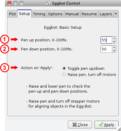
- From the Setup tab, select “Toggle pen up/down,” indicated as (3) above. Then, click apply several times. The servo motor should move back and forth between two different positions.
- If your servo motor does not move, check that it’s connected to the right location and that the EBB has both power (from the plug in power supply) and the USB connection to your computer.
- Adjust the two percentage values ((1) and (2) shown above) for the pen up position and pen down positions such that:
-
- The pen arm is roughly horizontal, or very slightly below, when “down”
- The pen arm is very slightly above horizontal when in the “up” position
- Typically you want about 5 mm (a little under 1/4″) of total travel between the two positions.
- This amount of range may correspond to only a few percent difference between the up and down positions.
2. Set the motors. From the Setup tab, select Raise pen, turn off motors, then click Apply. This will unlock the motors, leaving them free to rotate, with the pen arm in the right position to put a pen over the egg.
3. Set the pen arm arc depth. That is to say, a different setup is needed if you’re printing on a sphere (like a golf ball) than if you’re printing on an egg-shaped object. The pen motor mounts with screws through slots, so that the depth of its drawing arc can be changed. On the inside of the chassis sidewall, there’s a gauge and some simple illustrations indicating rough positions for the motor. A chicken egg will typically use the center position; a sphere or nearly-spherical glass bulb (such as a standard lightbulb or a christmas ornament) will use the top position; a duck or goose egg may need the bottom position. Gently loosen the screws, slide the motor to the correct height, and then gently tighten the screws.
4. Align the headstock. The headstock (containing the egg motor) is connected to the chassis side walls with 3 screws on each side. Gently loosen those screws until the headstock barely slides; usually about half a turn on each. Slide the headstock until the equator (the widest part) of an egg placed against the headstock is directly beneath the pen arm. More precisely, if an imaginary line comes straight out of the pen motor shaft, it should intersect the equator of your object. Once you like the position of the headstock, set the egg aside and tighten the headstock screws on each sidewall, taking care to ensure that headstock meets each chassis side wall at the same place on the gauges.
5. Align the tailstock. The tailstock (containing the spring-loaded plunger) is connected to the sidewalls with screws, just like the headstock. Gently loosen the screws on each side until the tailstock barely slides. With an egg placed against the headstock egg cup, set the egg’s north pole in the plunger egg cup, and then slide the tail stock until the plunger O-ring (between the two sides of the tailstock) is roughly 1/2 to 3/4 of the way to “fully compressed.” Once you like the position of the tailstock, tighten the tailstock screws on each sidewall, taking care to ensure that tailstock meets each sidewall at the same place on the side scales.
6. Place a pen in the pen arm. Uncapped, point down, (of course) so you can judge how it will align with the egg. Tighten the thumbscrew to fix the pen position. Rotate the pen arm until it is vertical. You may want to raise the pen arm to its maximum vertical position at this stage, by loosening the large nylon thumbscrew (the one that attaches the proximal pen arm to the pen arm backer), sliding the pen arm all the way up, and tightening the thumbscrew again.
7. Mount An Egg in the EggBot. (Obviously doesn’t have to be an egg, per se. But we tend to call an object in the Egg-Bot an “egg,” since it sounds better than “spherical or ellipsoidal print media.”) See the section below for how to mount the egg in the ‘bot.
8. Set the pen arm height. Adjust the pen height such that the pen such that the tip is just above (say, 1-3 millimeters) the surface of the egg when it is in the “up” position. To do this, you may need to raise or lower the pen arm, by loosening the thumbscrew that holds the proximal pen arm to the pen arm backer, and then tightening it when the pen is in the right place. For finer adjustment, you can loosen the thumbscrew that mounts the pen into the distal pen arm, and adjust the pen itself up or down to the correct position. Once you think that you have the pen arm right, it’s helpful to swivel the pen arm back and forth over the egg to check clearance.
Mount An Egg in the Sphere-o-BOT
- Remove pen (if any) from the pen arm.
- Start with a clean, dry, room-temperature, raw egg. (If it’s not an egg, it’s likely to already be room temperature, dry and raw. Make sure that it’s clean, too!)
- Dry, so your marker will adhere.
- Room-temperature, so that your egg will stay dry.
- Raw, so that you can empty it out afterwards, in the event that you get a good one. (Yes, you could hard-boil your eggs, but then you’ll have to break them to get the centers out. Or you could empty them first, but that’s an awful lot of effort if an egg doesn’t turn out right.)
- Clean, so that ink flow is not affected by grease on the surface. You may even want to use rubber gloves for handling your eggs to keep greasy finger prints off (especially important if using technical pens with very fine nibs.)
- Pull back the plunger and roughly center the end of the egg on the headstock. Gently return the plunger to the other end of the egg. Spin the egg to see if it is centered, and adjust its position in the two egg cups as necessary. (You want as little wobble as you turn your egg as possible — more wobble will lead to uneven drawings.)
Preparing your drawing
It’s best to start with a document that’s 800 pixels tall by 3200 pixels wide — you can use the Sphere-O-bot Template from the set of example files as a good starting point. Sphere-O-bot draws paths — continuous lines — not bitmap images, and not solid filled regions. Certain object types are automatically treated as paths, for example circles and rectangles. Other types of objects that are made of lines — like outlined text — may need to be converted to paths (Path menu > Object to path) before plotting. A good first plot might be the “Hello world” example file.
(If you have not already, you may also want to download the Sphere-O-bot Examples from the EggBot Releases page.)
Drawing on your Egg
- From the Manual tab, select Enable Motors, then click Apply. Then select Raise Pen then click Apply.
- Put a pen in the pen arm.
- Begin with vector art in inkscape.
- From the Plot tab, press apply, and the Sphere-O-bot should print the entire drawing.
If your stepper motors (Motor 1 and Motor 2) are weak, make high-pitch whining noises, exhibit jittery behavior, or produce inconsistent step sizes, you probably need to adjust the current setting on the Brain Shield (stepper motor drivers).
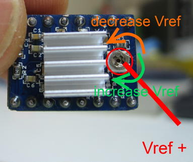
- There is a small current adjustment potentiometer (a flat little “knob” that can be turned with a small screwdriver) Use a tiny screwdriver to gently turn it in small increments. Enable the motors from the Manual tab of Eggbot Control if they are not already enabled. Turn the potentiometer clockwise until the motors provide moderate resistance to turning by hand– usually about 1/3 to 1/2 a turn.
- If the motors are moving but not performing correctly while plotting, you may prefer to begin a simple plot (for example, the “Hello World” example) and adjust the current while it is plotting. Note that the motors may behave differently while your screwdriver is actually touching the adjustment potentiometer.

Some MAKERs have had a problem recognising the Sphere-O-bot when using the INKSCAPE 0.48 (or 0.91) and the EggBot_240A.exe extension. Fix it replacing the original eggbot.py file for this one: eggbot.
The location of this file: [your hard drive unit]:\inkscape 0.48[or 0.91]\Inkscape\share\extensions
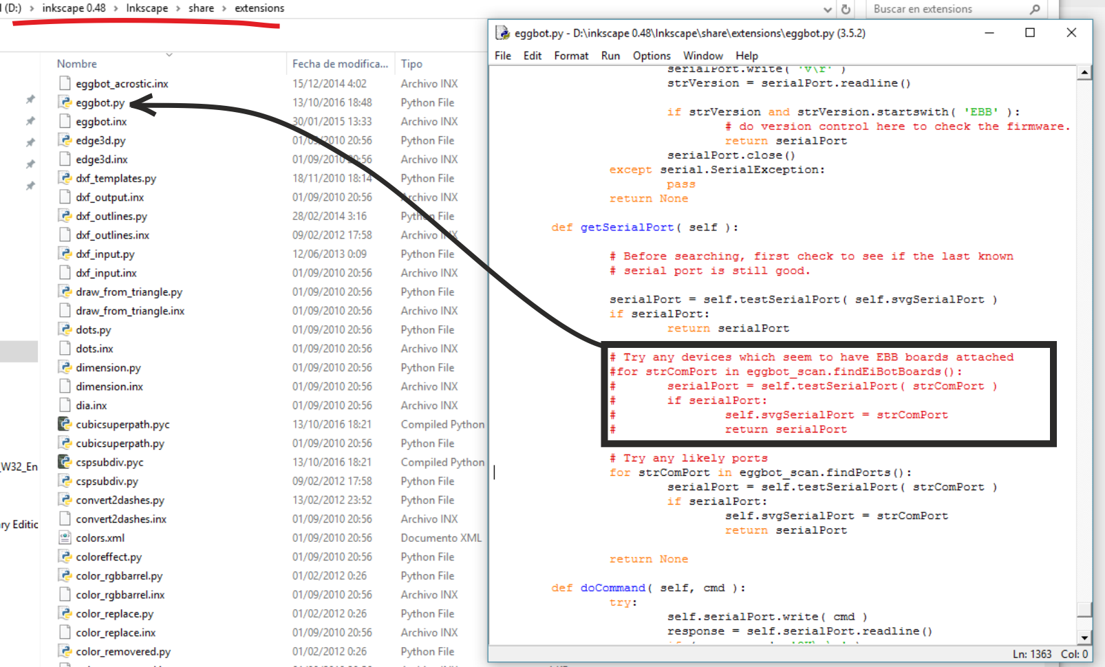
Above. what we have done: disable the “finding” procedure inside the eggbot.py

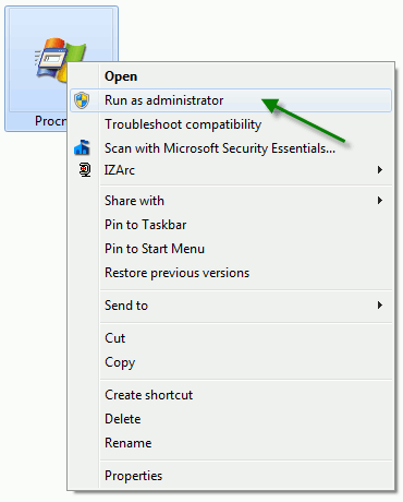
NOTE: Remember to run the Inkscape as ADMINISTRATOR if you are using WINDOWS OS!