“Short” version:
The B-robot (self balancing robot) reads his inertial sensors (accelerometers and gyroscopes integrated on the MPU6000 chip) 200 times per second. He calculates his attitude (angle with respect to the horizon) and compares this angle with the target angle (0º if he wants to maintain balance without moving, or a positive or negative angle if he wants to move forward or backwards). Using the difference between the target angle (let’s say 0º) and actual angle (let’s say 3º) he drives a Control System to send the right commands to the motors to maintain his balance. The commands to the motors are accelerations. For example if the robot is tilted forward (angle of robot is 3º) then he sends a command to the motors to accelerate forward until this angle is reduced to zero to preserve the balance.
The physical problem that B-robot solves is called the Inverted Pendulum. This is the same mechanism you need to balance an umbrella above your hand. The pivot point is under the centre of mass of the object. More information on Inverted Pendulum here. The mathematical solution to the problem is not easy but we don’t need to understand it in order to solve our robot´s balance issue. What we need to know is how should do to restore the robot´s balance so we can implement a Control Algorithm to resolve the problem.
A Control System is very useful in Robotics (an Industrial automation). Basically it´s a code that receives information from sensors and target commands as inputs and creates, in consequence, output signals to drive the Robot actuators (the motors in our example) in order to regulate the system. We are using a PID controller (Proportional + Derivative + Integral). This type of control has 3 constants to adjust kP,kD,kI.
 HOW A PID CONTROL WORKS: TAKE A LOOK TO THIS LESSON IN THE ACADEMY
From Wikipedia: “A PID controller calculates an ‘error’ value as the difference between a measured [Input] and a desired setpoint. The controller attempts to minimize the error by adjusting [an Output].”
So, you tell the PID what to measure (the “Input”) ,where you want that measurement to be (the “Setpoint”,) and the variable you wish to adjust to make that happen (the “Output”.) The PID then adjusts the output trying to make the input equal the setpoint.
For reference, a water tank we want to fill up to a level, the Input, Setpoint, and Output would be the level according to the water level sensor, the desired water level and the water pumped into the tank.
B-robot EVO CONTROL LOOP
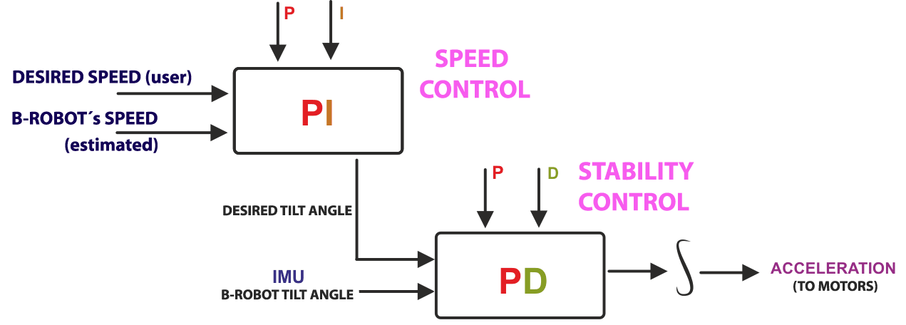
kP is the Proportional part and is the main part of the control, this part is proportional to the error. kD is the Derivative part and is applied to the derivative of the error. This part depends on the dynamics of the system (depends on the robot,´s weight motors, inertias…). The last one, kI is applied to the integral of the error and is used to reduce steady errors, it is like a trim on the final output (think in the trim buttons on an RC car steering wheel to make the car go totally straight, kI removes the offset between the target required and the actual value).
On B-robot the steering command from the user is added to the motors output (one motor with a positive sign and the other with a negative sign). For example if the user sends the steering command 6 to turn to the right (from -10 to 10) we need to add 6 to the left motor value and subtract 6 from the right motor. If the robot is not moving forward or backwards, the result of the steering command is a spin of the robot. 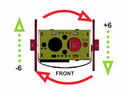
HOW TO ADJUST THE PID PARAMETERS OF THE B-ROBOT IN REAL TIME
By default, the value of the P,D and P,I parameters are as indicated below (paragraph extracted from the Original B-robot EVO code):
#Stability control
#define KP 0.19
#define KD 28
#Speed control
#define KP_THROTTLE 0.07
#define KI_THROTTLE 0.04
Now, the Official jjRobots APP (available at GOOGLE PLAY, see the link below) allows you to adjust, in real time, the P,D and P,I values of your B-robot EVO.
This will help you to:
- Adjust its behaviour
- Improves its balance (have you modified the B-robot frame and/or moved its centre of gravity and want to increase its balance? Play with the sliders and get the perfect parameters)
- Understand how a PID control works in a real balance system
![]()
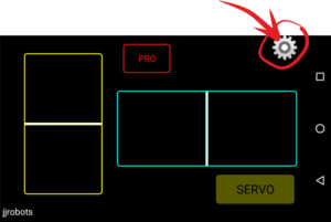
To access to this parameters configuration page, after installing the APP, select the B-robot EVO and tap on the gear on the top right corner:
Below, the slider mapping scheme. On the left side, the P and D (Stability control) and on the right side the P and I parameters of the Speed control.
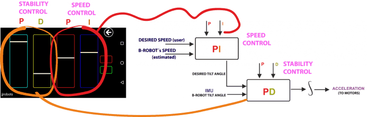
What you are doing sliding each horizontal bars is to multiply the current (set in the Arduino CODE) P,D and P,I values from 0 to 2.
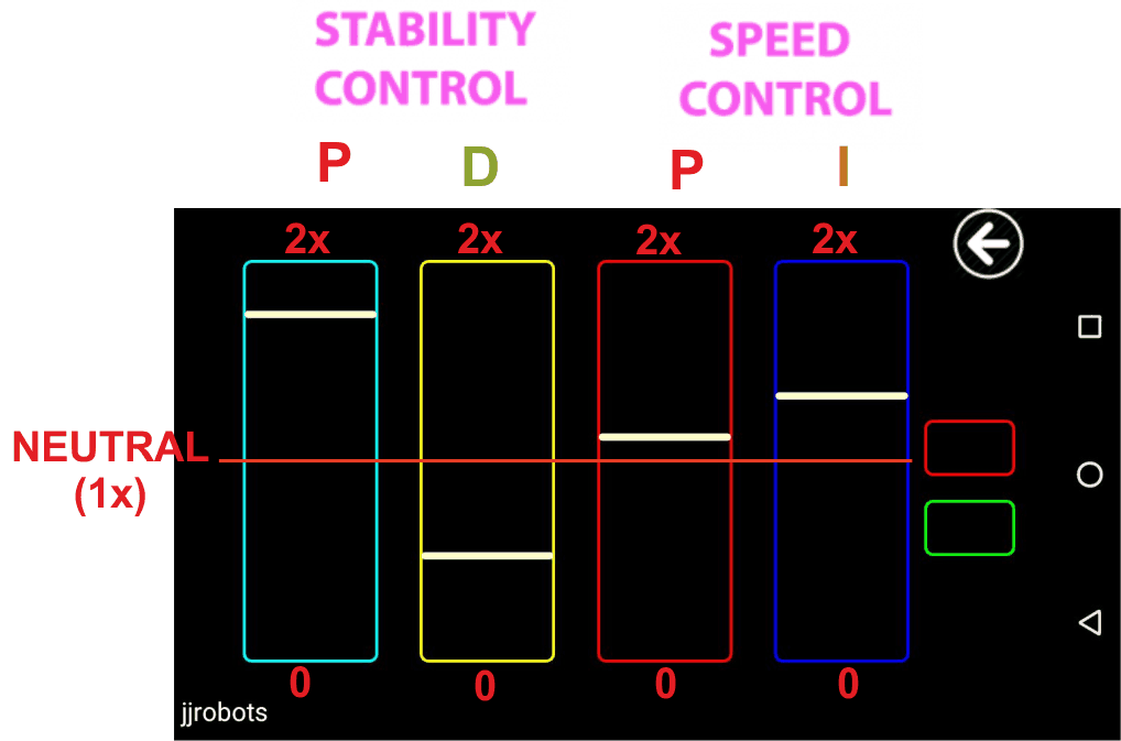
The slider multiplies the current values (set in the B-robot CODE) of every parameter (P,D and P,I) by 0 to 2x depending on its position. In the neutral position, the parameters stay unaltered. The horizontal bar at the Bottom of the slider= x0, Top: x2
Questions? Comments? go to the B-robot community and share your thoughts
![]()