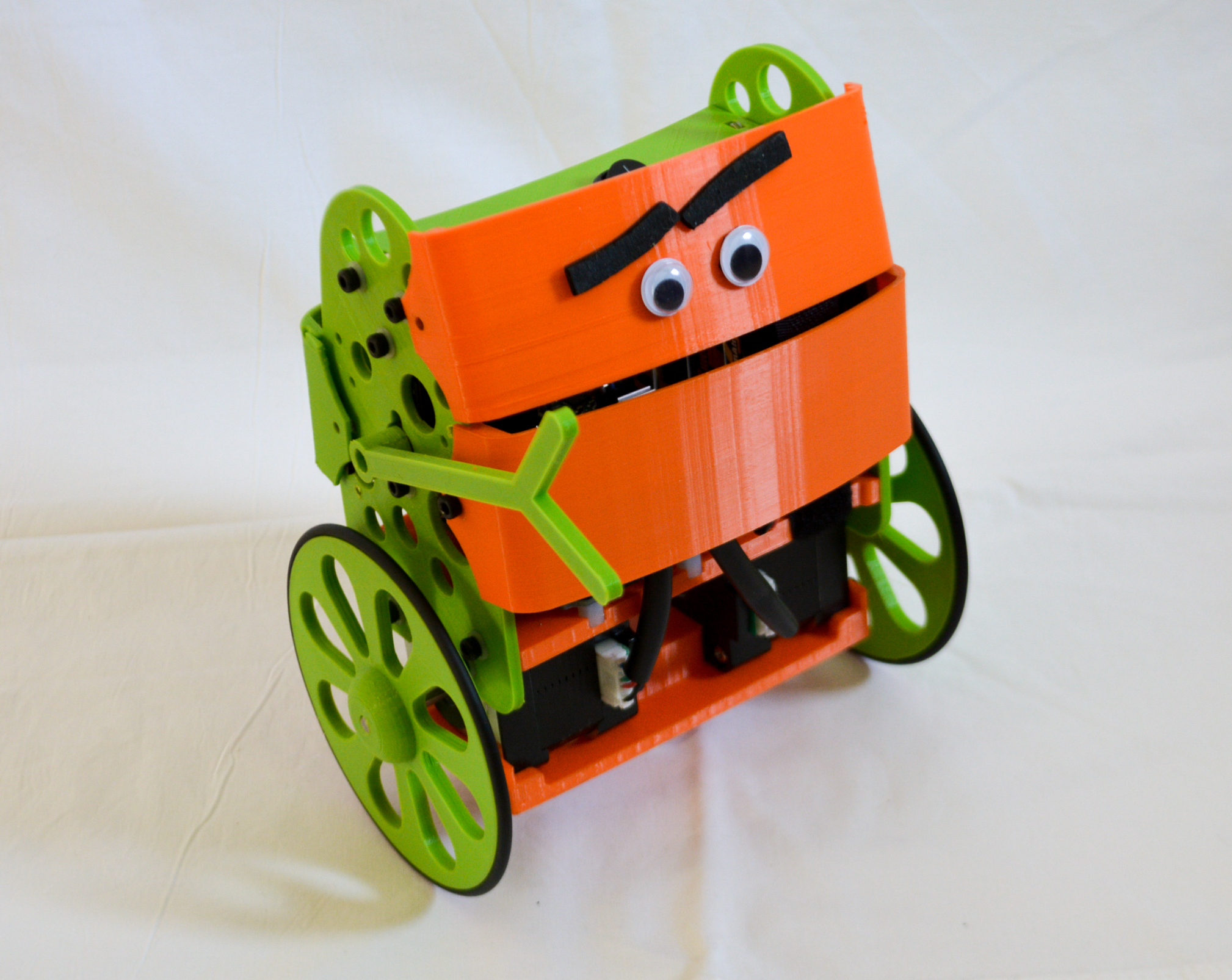
Let´s start. This is what you get after opening the B-robot EVO KIT box:
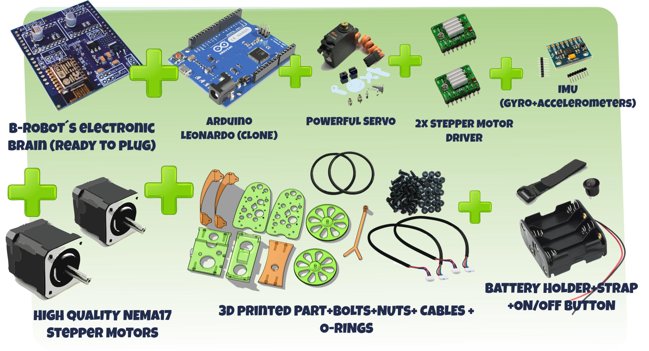
KIT´S PACKING LIST:
- B-robot electronic BRAIN v3.0 (already programmed)
- Arduino Leonardo (CLONE) + USB cable
- 2x High quality NEMA17 stepper motors
- 2x Stepper motor driver+cables
- IMU (gyro+accelerometers)+cable
- 3D printed parts + rubber O-rings
- Powerful servo: CORONA metal gears SERVO
- Battery holder + battery strap
- Bolts* +nuts +motor cables +ON/OFF switch needed to set everything up
* In this assembly guide you will see hexagon head bolts but you might receive instead ,with your KIT, Phillips head bolts
Uploading the ARDUINO CODE to the ARDUINO LEONARDO
(skip this step if you got the Plug & Play B-robot EVO kit version)
- Open your Arduino IDE
- Open the main code in /BROBOT/BROBOT.ino
- Connect your Leonardo board with the USB to the PC
- Note: If this is the first time you connect a Leonardo board to your PC maybe you might need to install the driver.
- Select the board Leonardo (tools->board)
- Select the serial port that appears on the tools->Serial port


Assembling the B-robot EVO
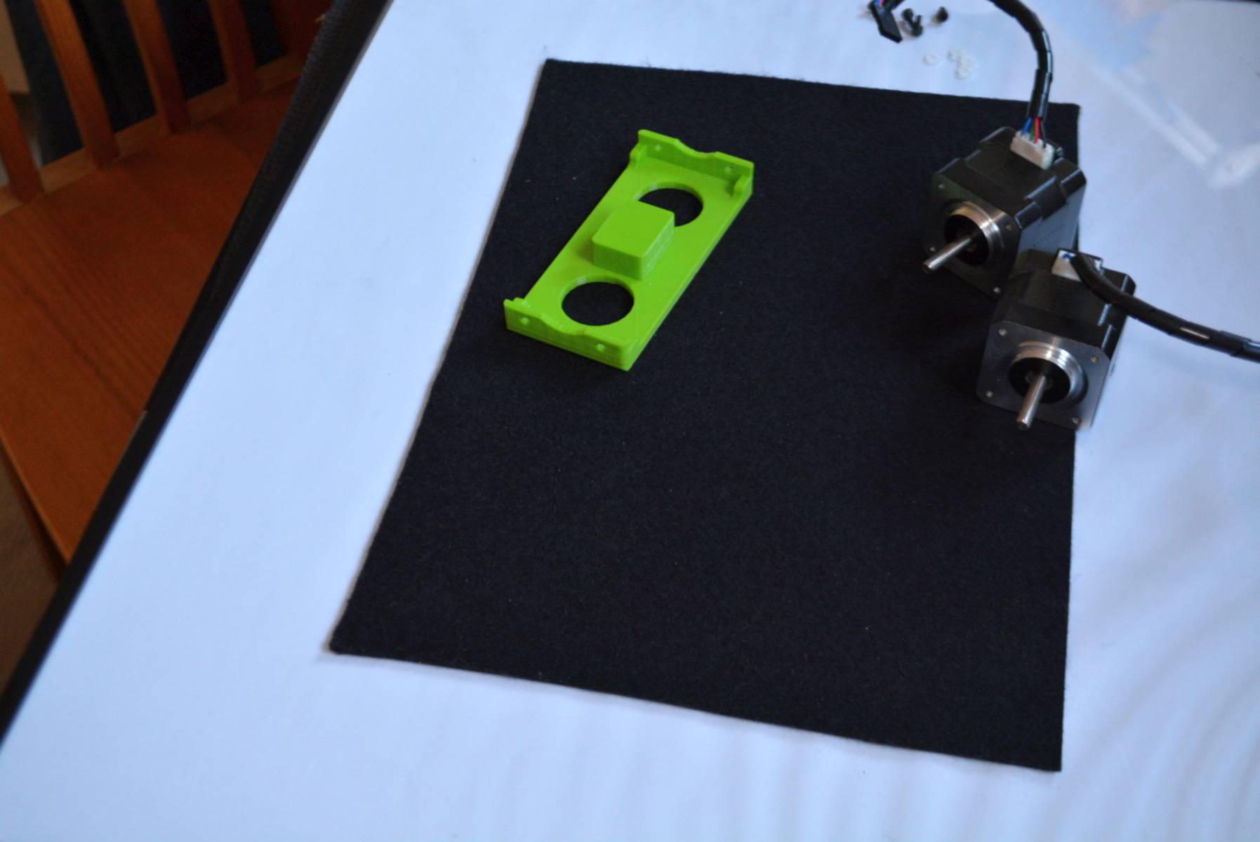
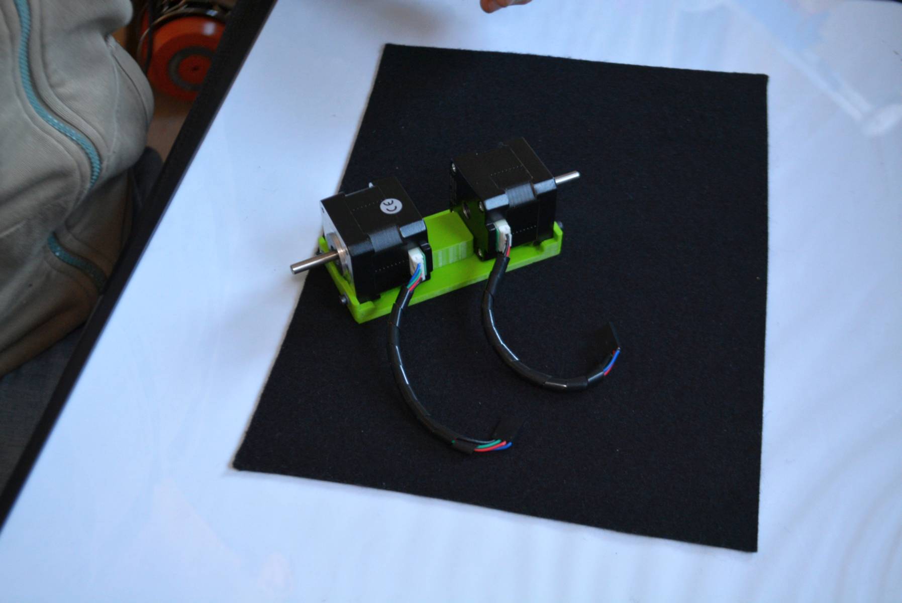
First step. take the motor shelf and the two stepper motors. You will need 2x 6mm bolts to fix both motors to this shelf (the type of bolt´s heads might vary depending of its size).
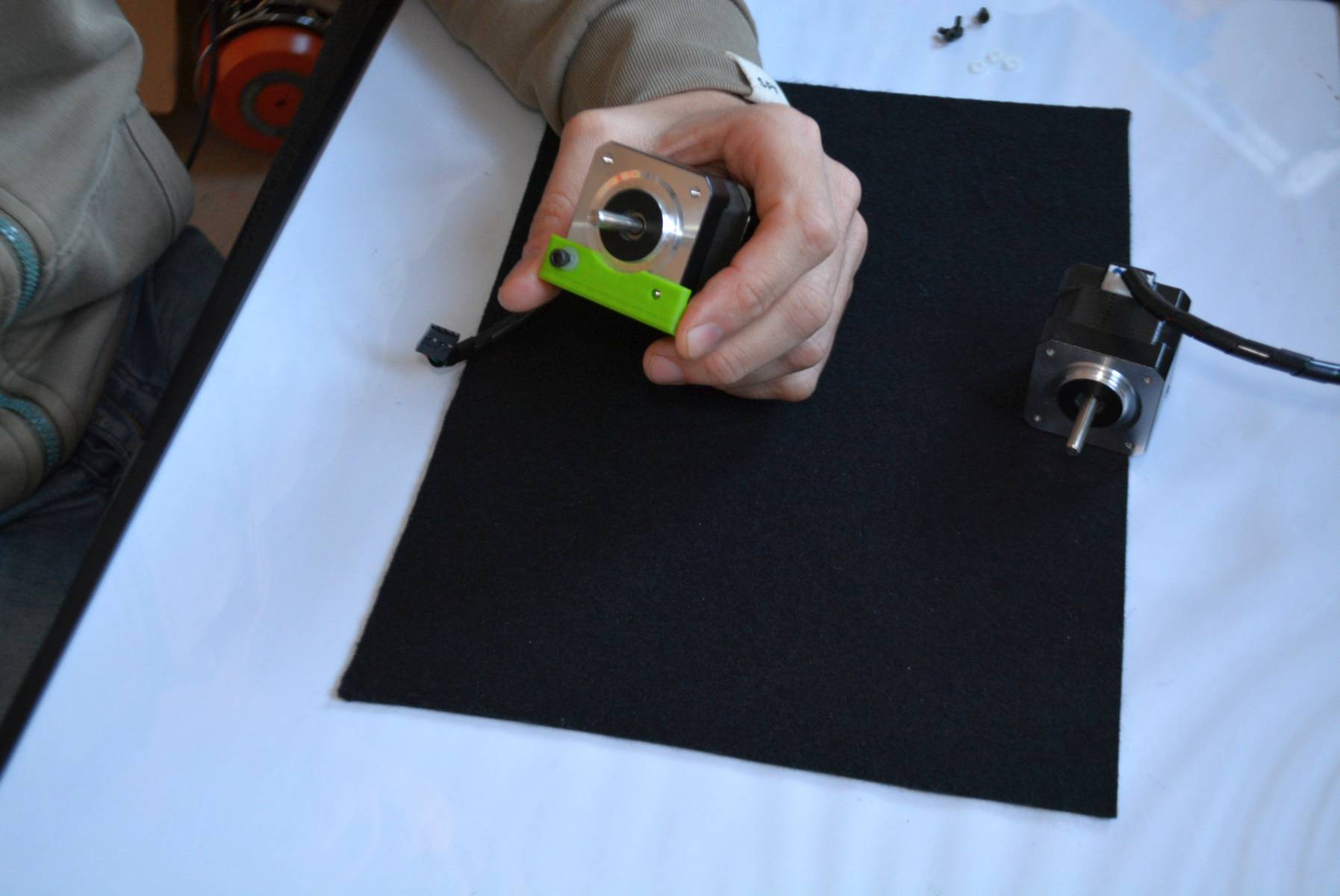
Like this
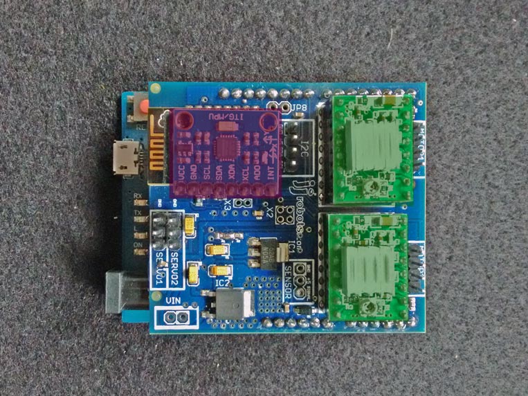
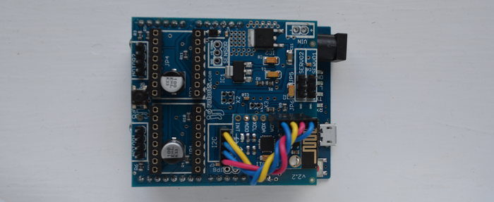
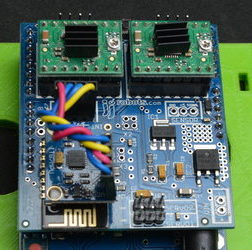
That was easy. Next: Use the double side tape to fix the IMU to the top of the WIFI module. Place the MOTOR DRIVERS in their place. Pay attention to their orientation 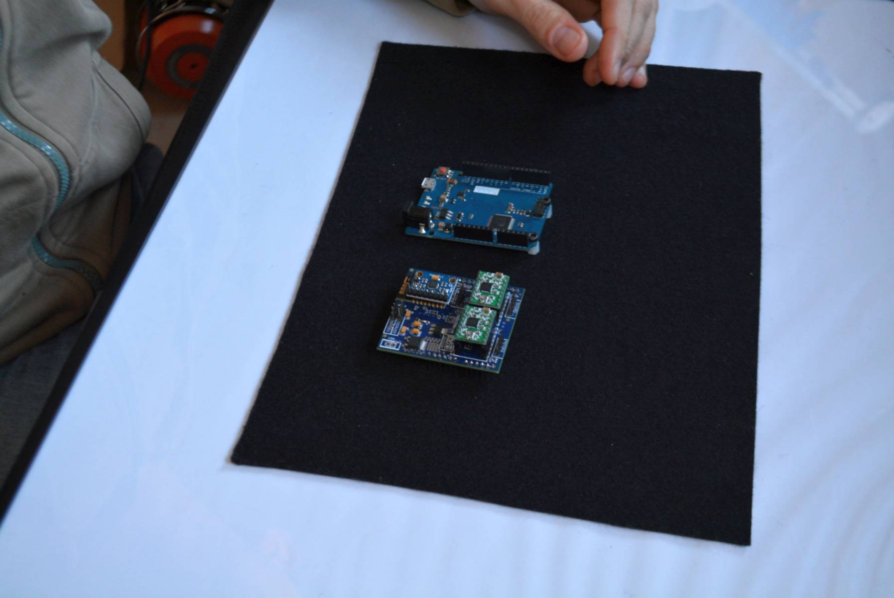
IMU´s (MPU6050) pin headers to the inner side of the PCB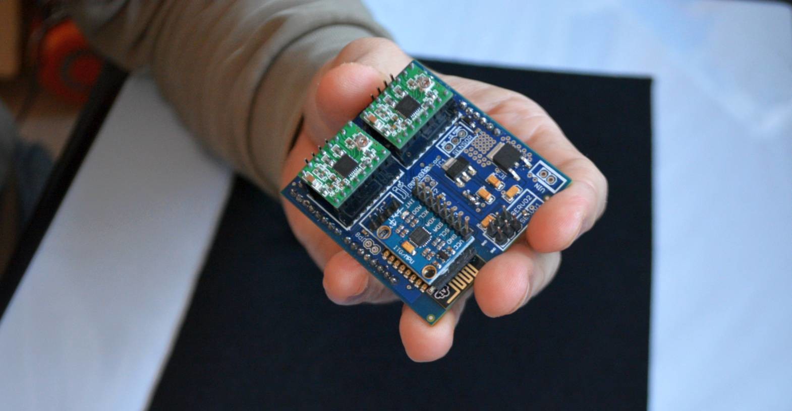
In detail (pay attention to the modules orientation):
The double side tape used to fix the IMU to the WIFI module shown below:
Now, according to the electronic diagram shown below. Connect the IMU to the B-robot BRAIN SHIELD using the cable provided. PAY ATTENTION TO SIGNAL CABLES AND VOLTAGE POLARITY
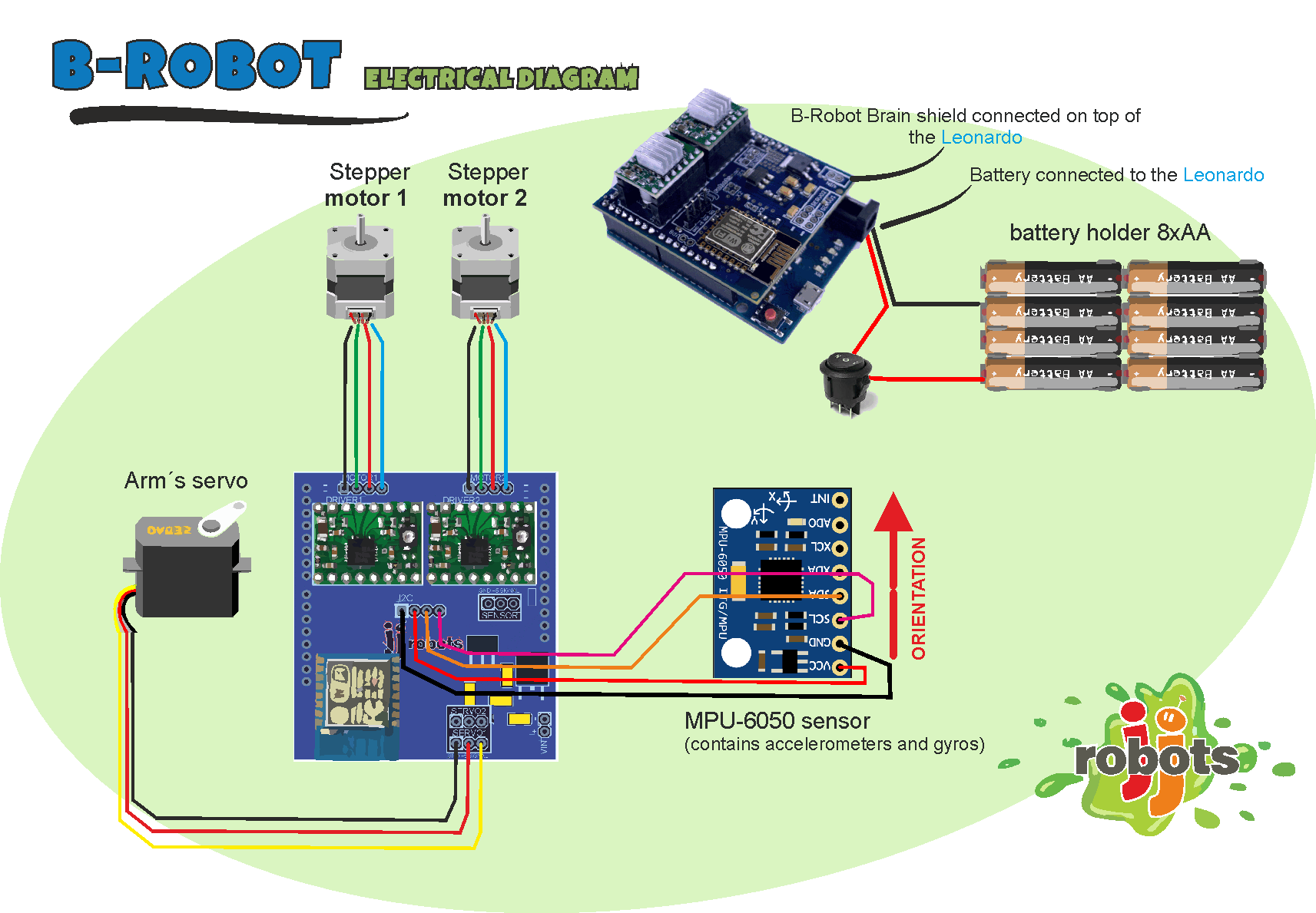
IMU > BRAIN SHIELD Connections:
- SDA -> SDA
- SCL-> SCL
- GND ->GND
- VCC->VCC
We have manufactured a custom cable to connect the IMU to the Brain Shield (you will get this cable with the KIT). It is quite difficult to connect it backwards but even so, be careful.
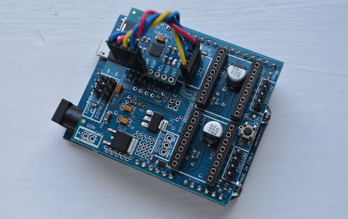
Twist the BUS cable as indicated in the photos when you are connecting it.
Check the connections TWICE.
NOTE: the i2C cable is short. Very short. We want to get rid of the EM interference created by electromagnetic sources (coils, fluorescent lamps, the own B-robot motors…) so, the shortest the cable, the best.
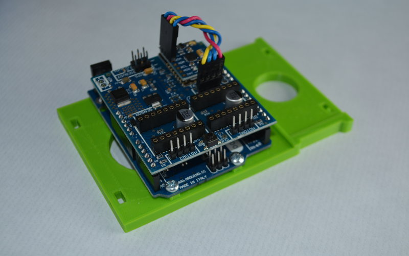
Place the Brain SHIELD+Leonardo on the MIDDLE SHELF. Use two 6mm bolts. See the detail below:
Servo TIME! Use the U shaped plastic part as the servo´s holder. This will increase the general sturdiness of the ARM. Fix it using two large bolts (+nuts).
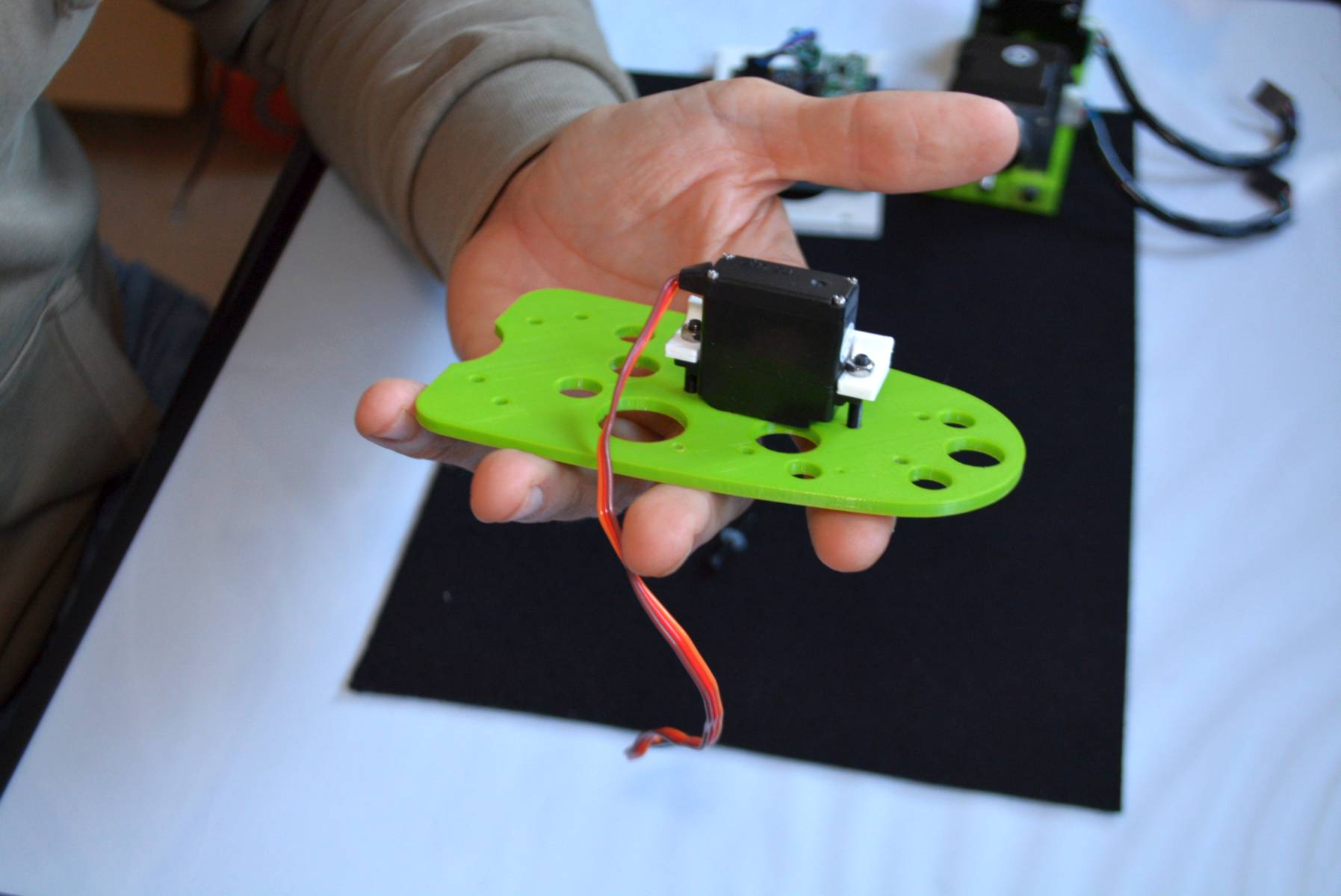
Nice. The B-robot´s lateral are symmetrical, so doesn’t matter which one you have picked.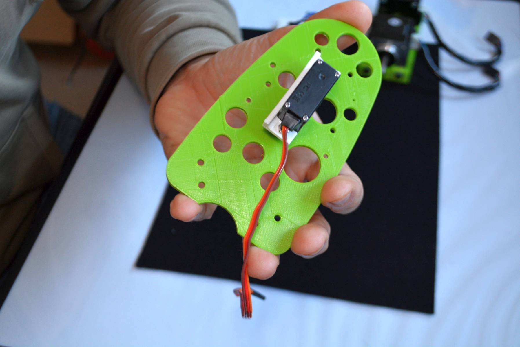
Yes, nice… The metal gear has to be centred in the hole.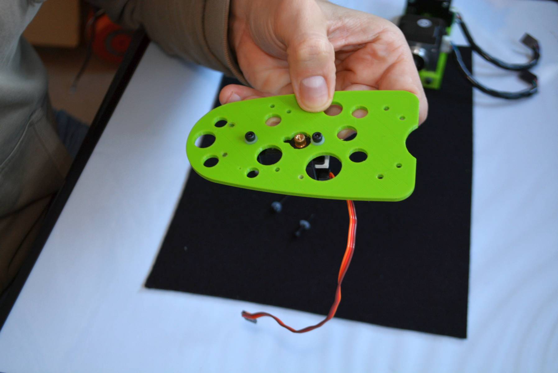
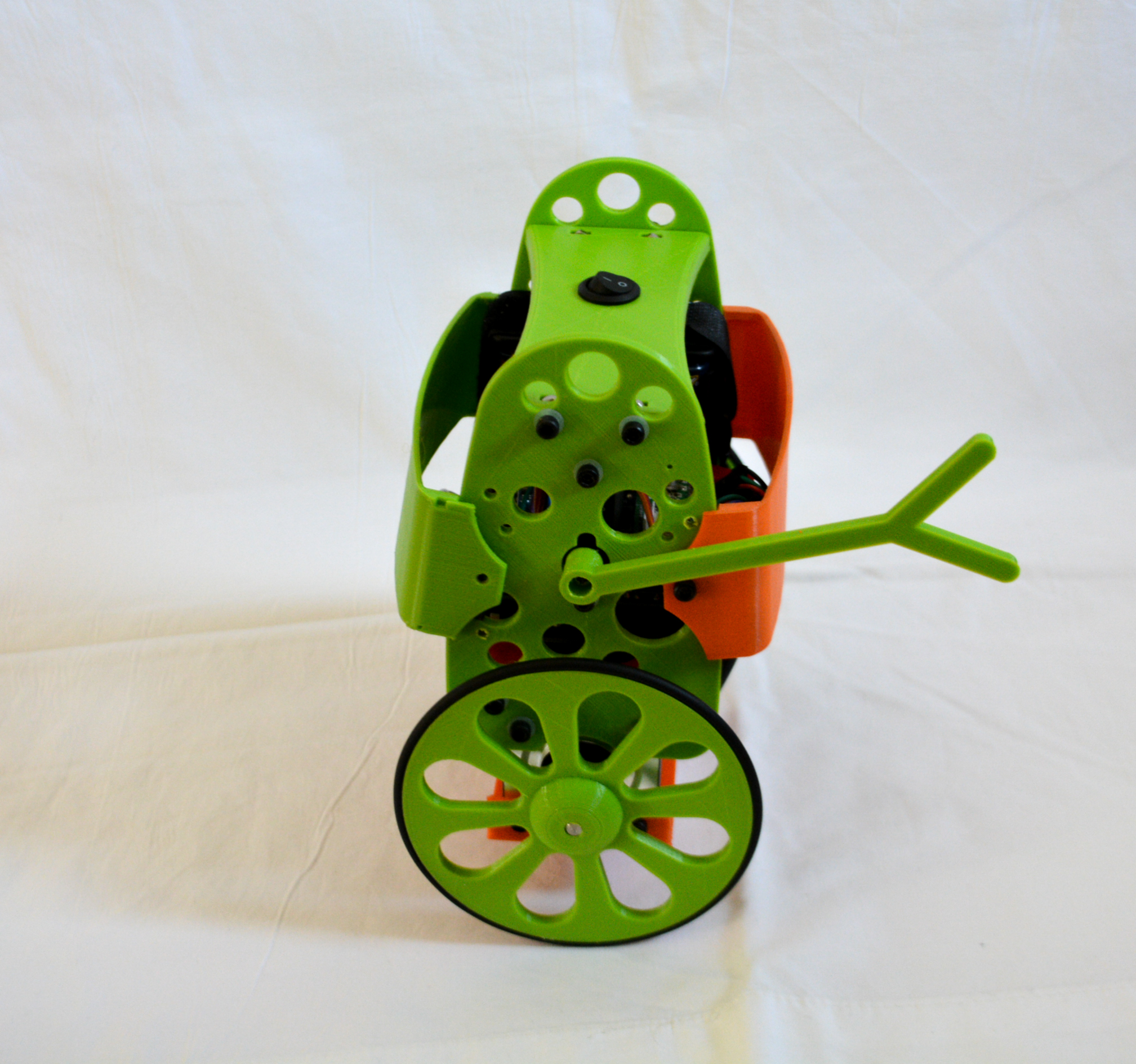
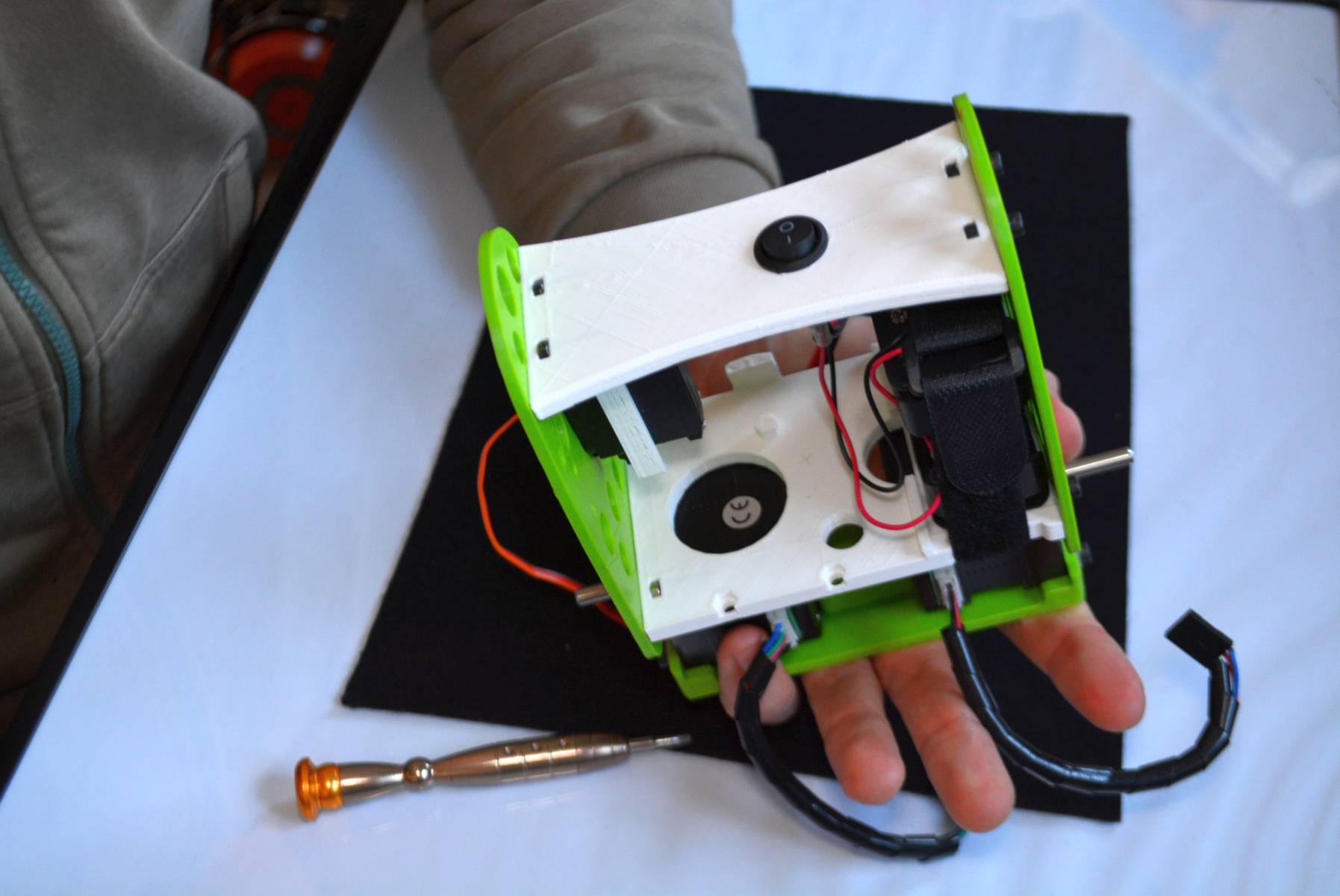
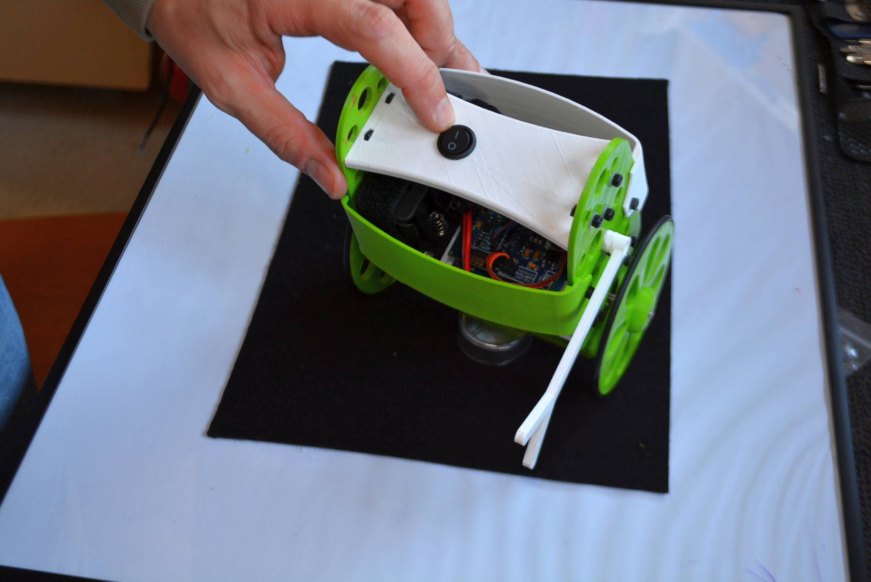
Top shelf: The ON/OFF button shelf.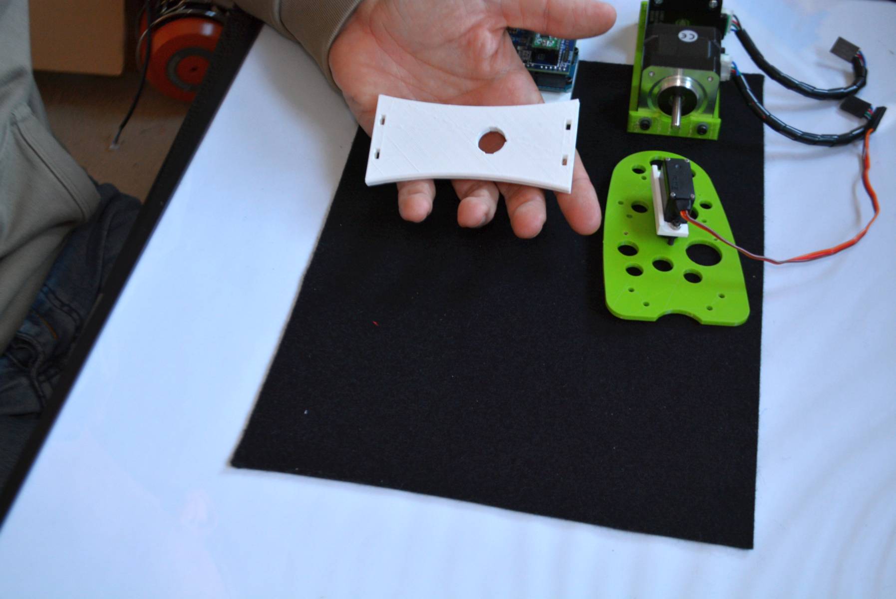
Push the button into its hole. 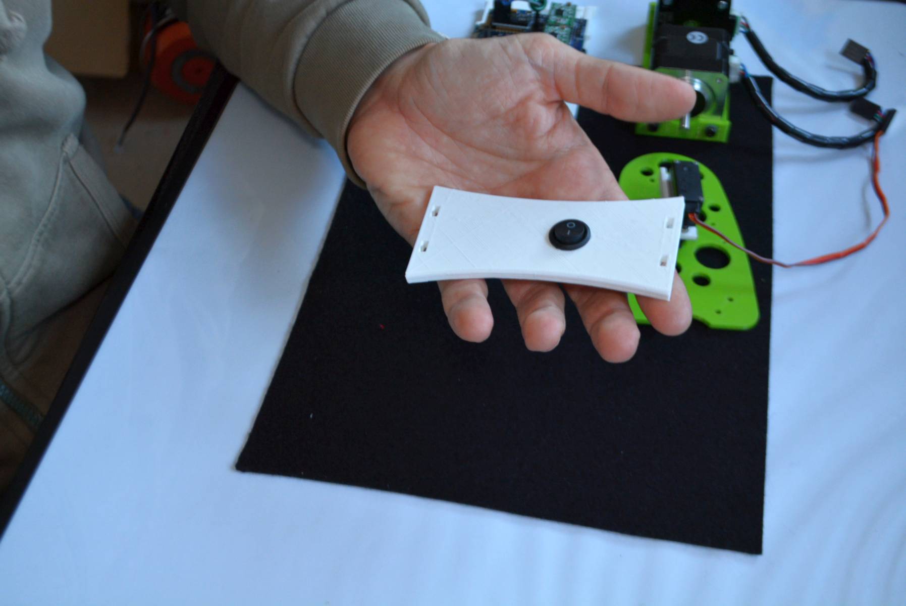
Connect the spades plug to the switch bottom. There is no way to make a mistake here. The switch will let the current pass… or not 🙂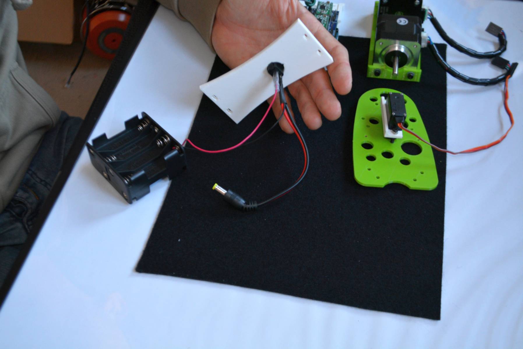
The battery holder will go like this. Placed next to the Brain Shield. NOTE: we are constantly improving the KIT´s elements. You will probably receive with the KIT a slightly different Battery holder: do not worry about this.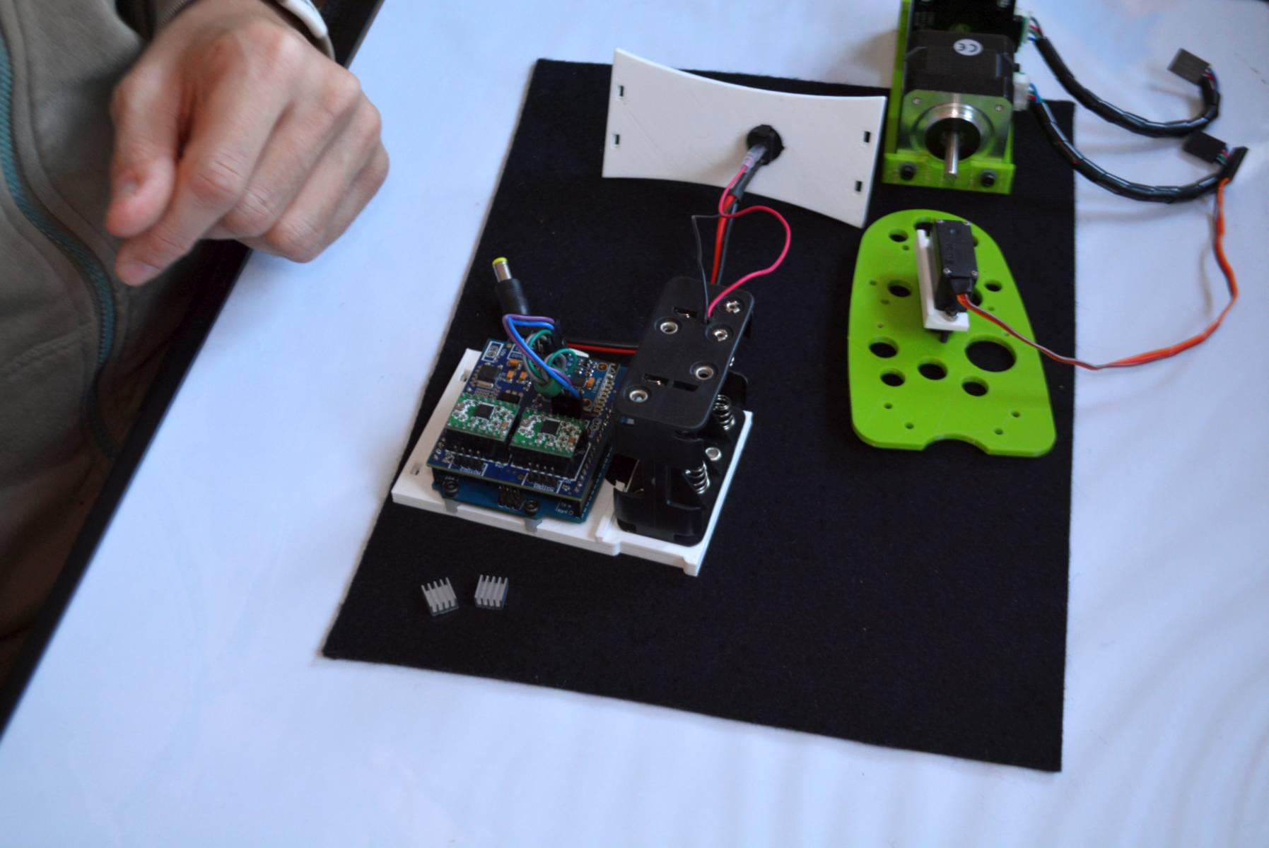
Place the heat sinks (black in this case) on the top of the STEPPER MOTOR DRIVERS
Fix the servo´s lateral to the STEPPER MOTOR using 2x 6mm bolts (NOTE: in the later B-robot EVO versions the washers are not needed to fix the 3D parts)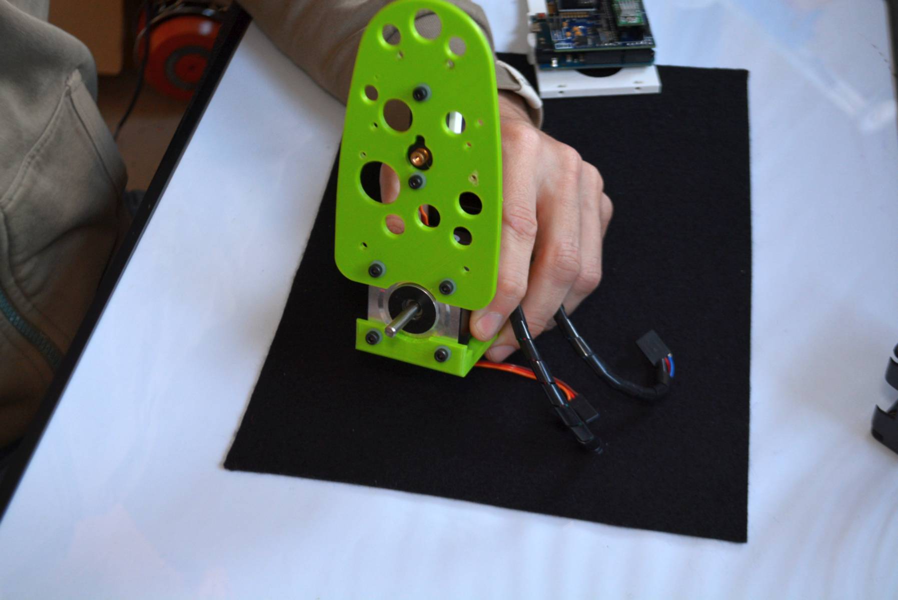
Now, using 2x16mm bolts, fix the BRAIN SHIELD shelf to the lateral. Remove previously the BRAIN SHIELD and BATTERY HOLDER.
The trick here: put inside the hole of the shelf, the nut. As long as you are screwing the bolt, the nut will push the shelf to the lateral and everything will be tight and sturdy.
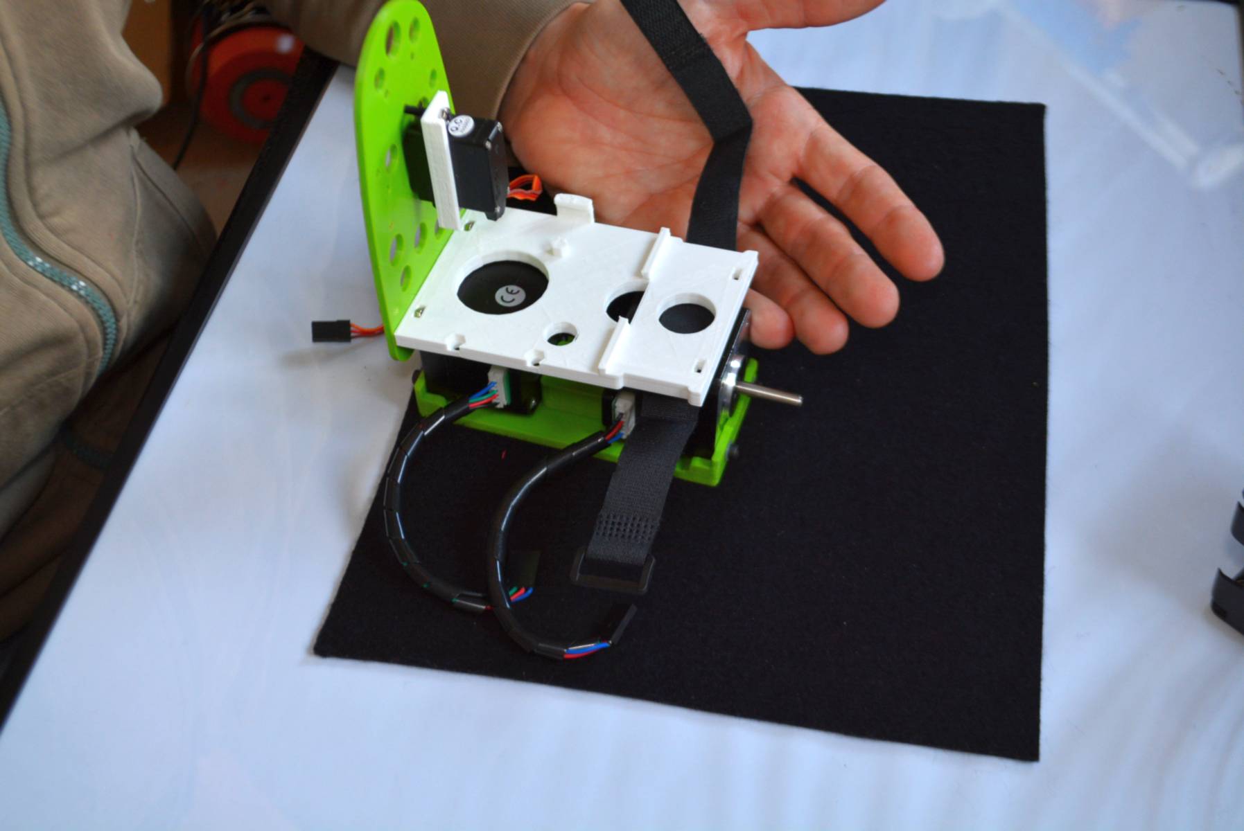
NOTE: pass the strap over the motor and beneath the SHELF (have a look to the photo below). The strap should be quite tight between the motor and the shelf. Do this better now.
Do the same with the other lateral.
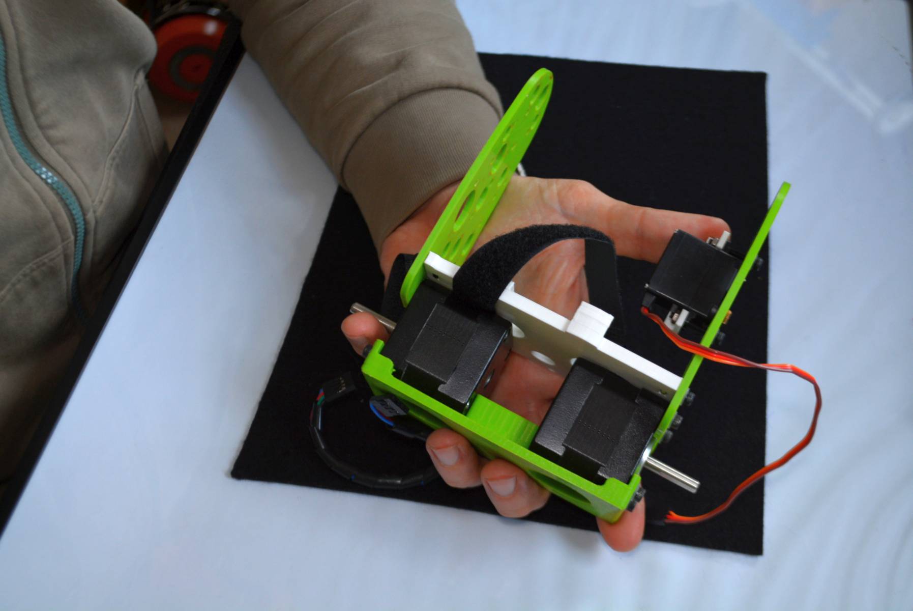
Place the battery holder and hold it using the strap.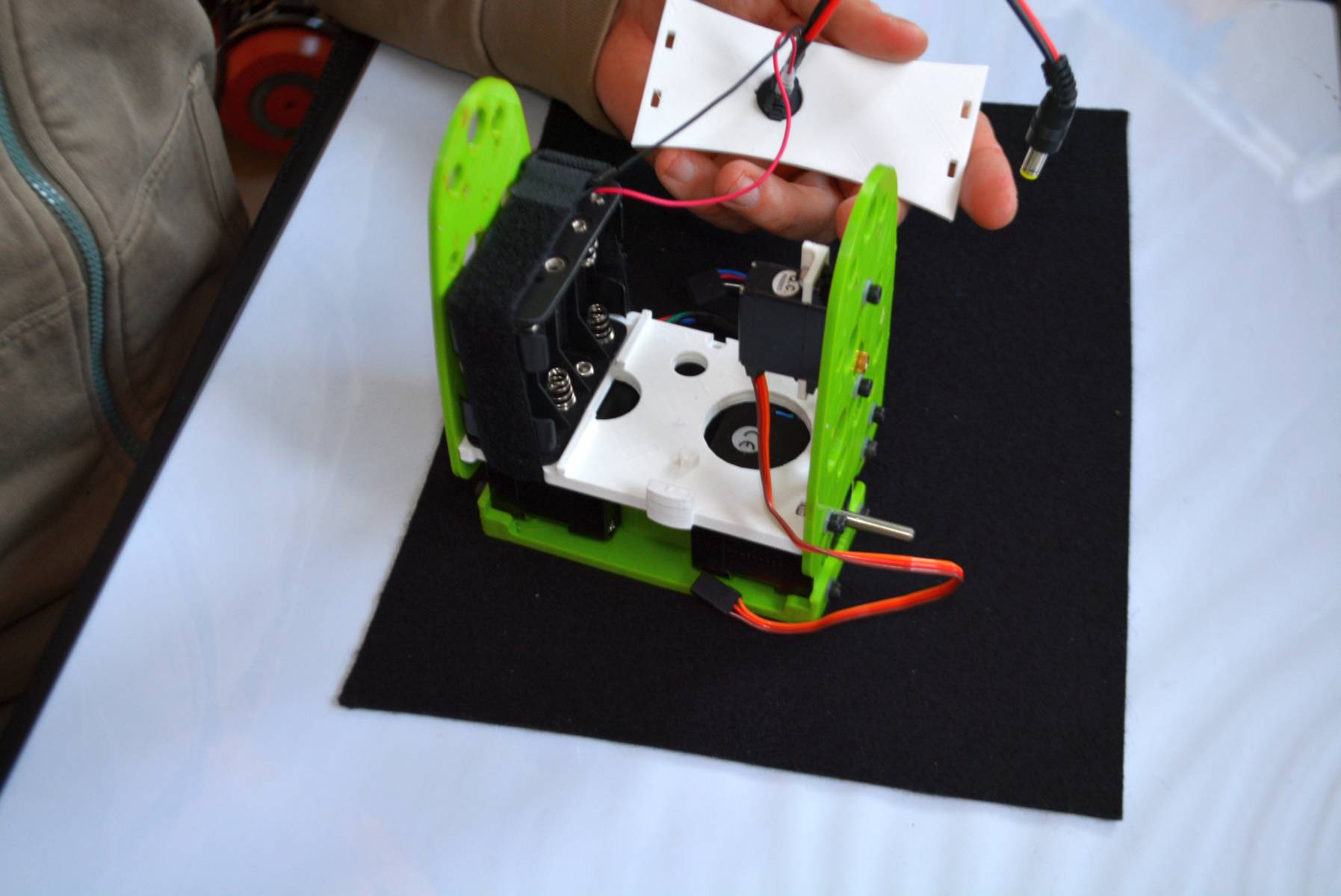
Do the same with the top shelf.
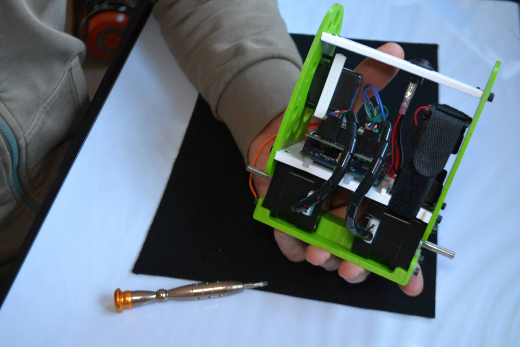
Connect the motor to the Brain Shield like this image indicates. The BLUE WIRES to the SERVO´s LATERAL SIDE.
- Motor on the SERVO SIDE: to the MOTOR2 connector on the BRAIN SHIELD.
- Motor on the battery side: to the MOTOR1 connector.
Almost there! Check the cables again (just in case). Is the IMU still fixed to the PCB? Everything seems to be OK?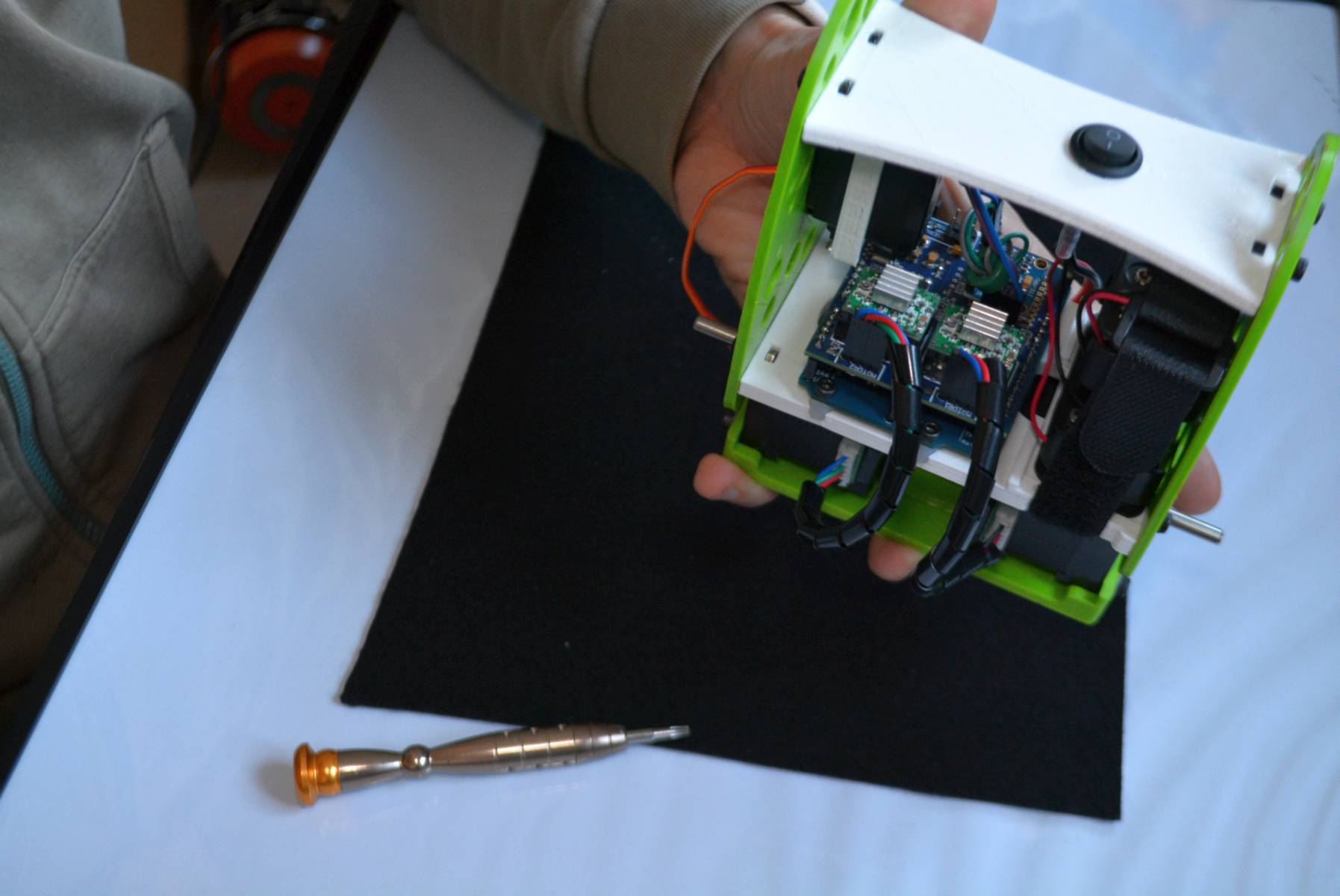
I am not using batteries in the photo, but this is the point where you should place them in the battery holder.
SERVO: PAY ATTENTION TO THE VOLTAGE POLARITY
SAFETY FIRST: Bumpers! Use 2x6mm bolts (no washers needed here) to fix the bumpers to the lateral of your robot.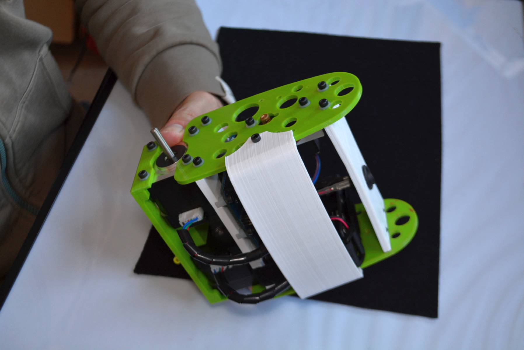
Looks nice…In this case, the GREEN BUMPER indicates the BACK of the B-robot EVO. The white one, the front.
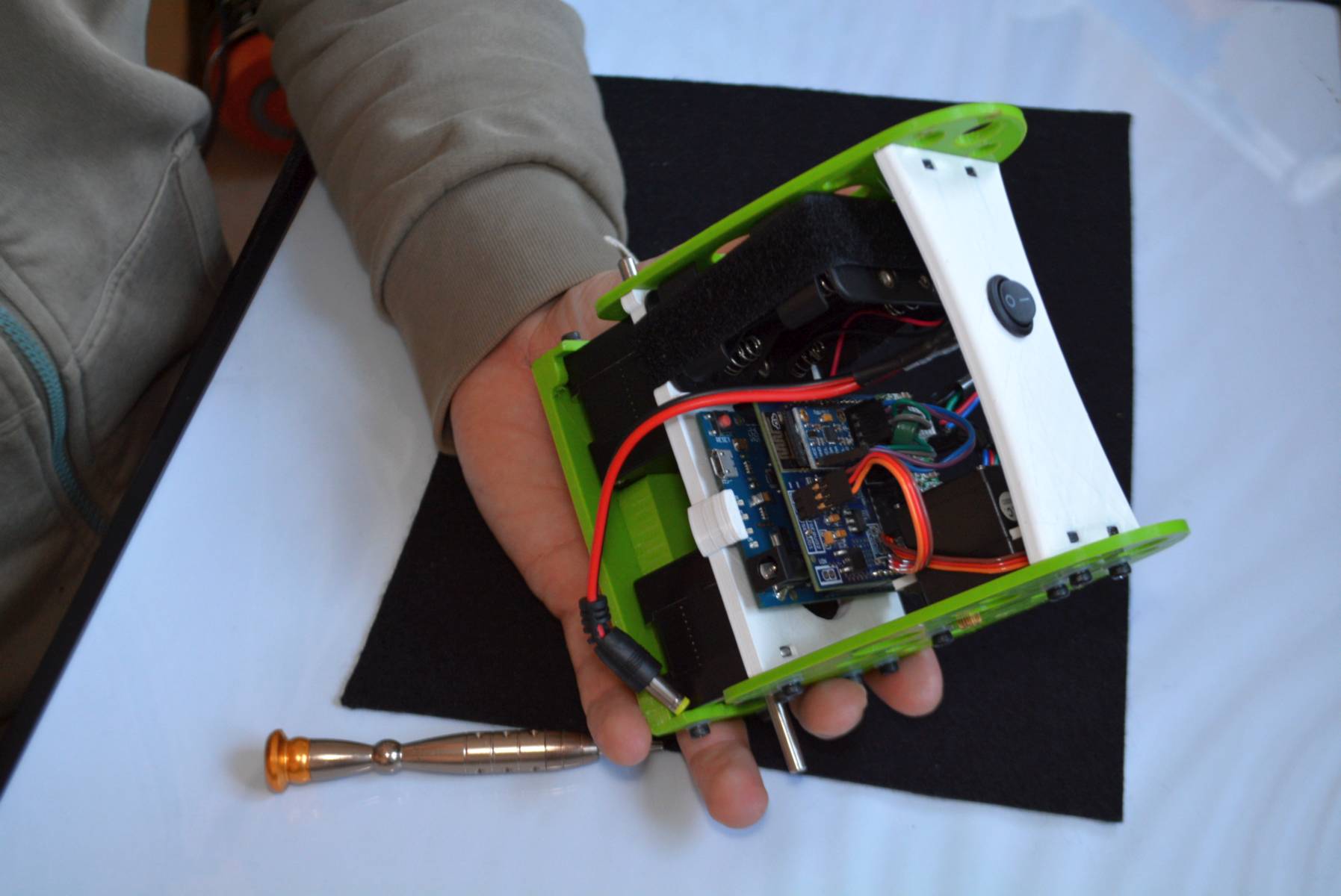
Because you would like to change the B-robot behaviour parameters via CODE (Acceleration, Speed, agresiveness….) ,you will need to connect the USB cable like this to the Arduino LEONARDO. This is how:
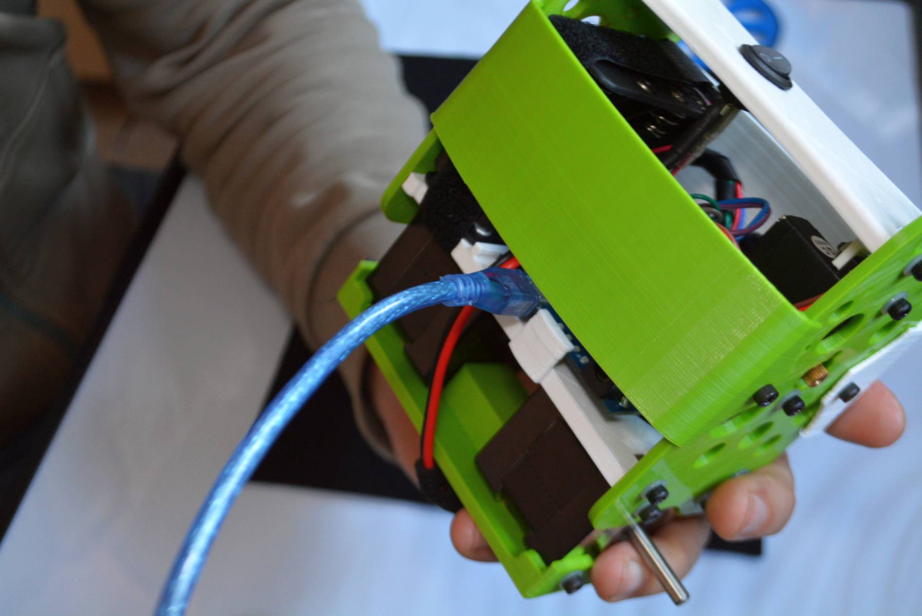
Time to connect the POWER CONNECTOR JACK coming from the battery holder+ON/OFF button to the Arduino Leonardo. CHECK the ON/OFF button is OFF before doing this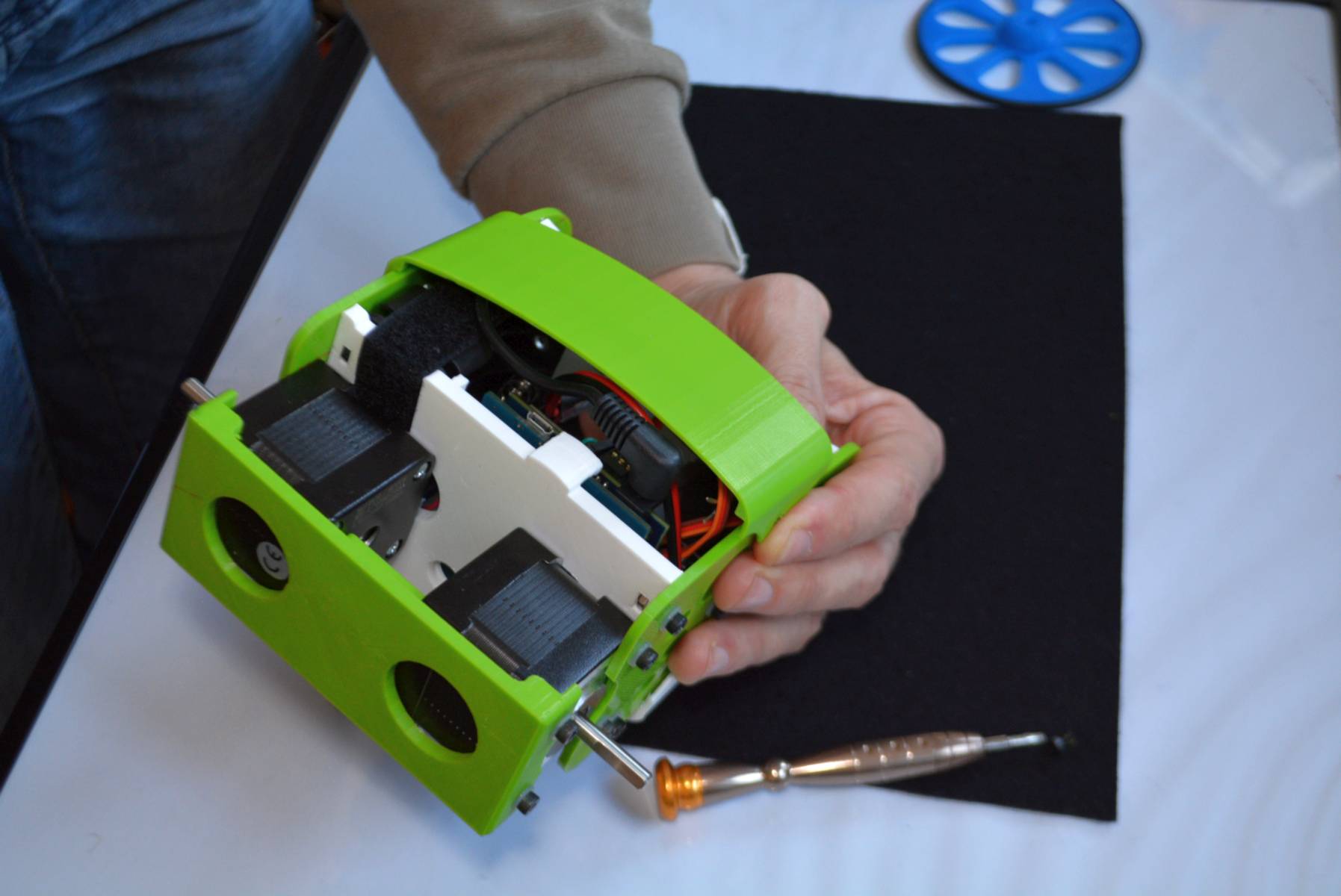
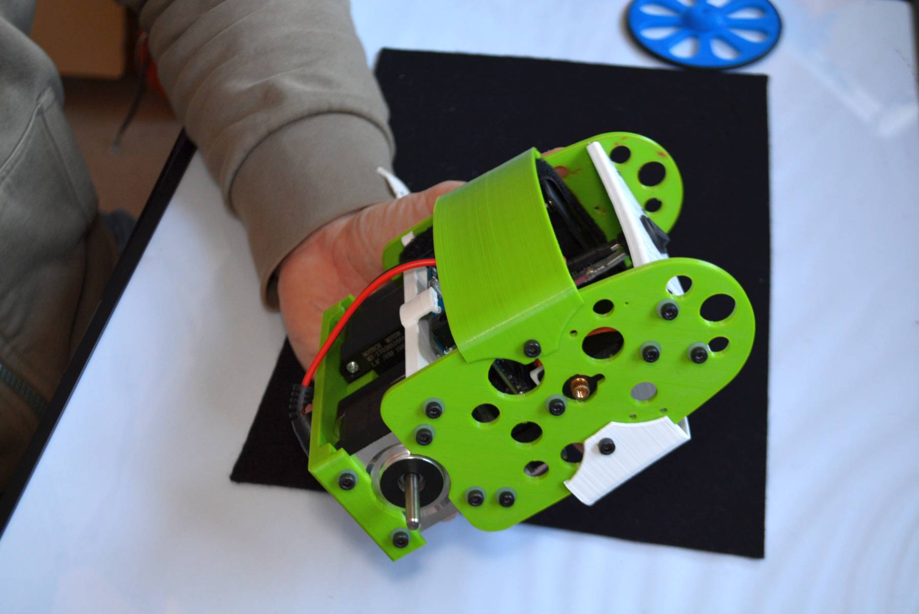
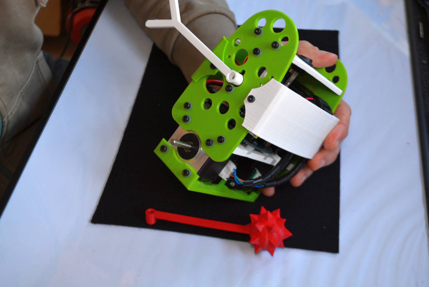
ARM: You will need to find the very end position of the servo. To do that, press the plastic arm to the servo´s gear and rotate it until you fell you have reached the end of its rotation. Well, the servo will rotate aprox. 180 degress, from the front of the B-robot to its back in an arc. So, place the arm according to this (you could need to re-adjust this a little later). If the rotation is limited clockwise, that means that the ARM should be set pointing TOWARDS.
The wheels: Pay attention to the D-shape of the wheels hole. The stepper motors axis is D-shaped too: there is only one way to fix it. Use a small hammer and some soft fabric/rubber to push the wheel throughout the axis. You might need to glue the rubber o-rings to the plastic wheels (depending on your aggressiveness controlling your B-robot EVO). Cyanoacrylate glue (Loctite or similar) will do the job perfectly.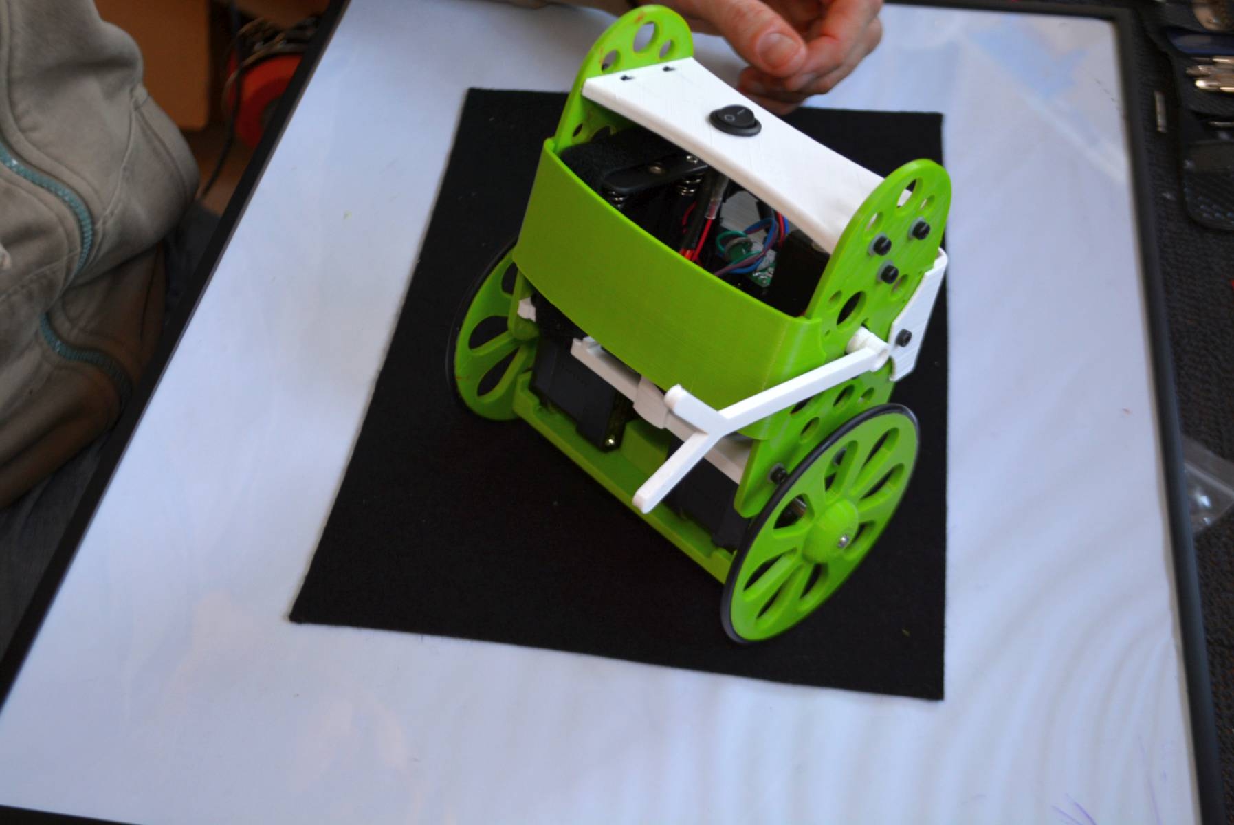
DONE!
If everything went fine, you only need to lay down the B-robot EVO, switch it ON and leave it static for few seconds on that horizontal position (meanwhile he calibrates the IMU by itself). After this time, the Brobot will start to spin a little its wheels and wave its ARM. That´s the moment when you can help him to stand up or use its arm (via remote control APP) to rise the robot.
1) Lay down the B-robot on a static horizontal place in order to let it calibrate itself after powering it up.
2) Turn the B-robot ON
3) Let the B-robot 10 seconds to calibrate itself. Once self-calibrated, B-robot will spin its wheels a little.
4) Time to stand up!: Use its arm or help it to stand up.
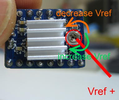
HINT: If the stepper motors do not have enough power to spin the wheels, adjust the current output in the A4988 stepper motor drivers rotating the screw indicated above
Remotely controlling the B-robot
iOS users. App Store App or TouchOSC :

We wanted B-ROBOT to be controlled by the user from almost any existing device, but we not wanted to develop a lot of different interfaces for different systems (Android, IOS, PC-windows…). Moreover, we decided to use existing (and powerful) protocols to control “things” and we found (some years ago) a protocol called OSC (Open Sound Control, more info here) used to control musical instruments like synthesizers. Very visual and powerful (we can display volume control, equalisers, lights…and create our own).
To remotely control the B-robot, we can use OSC protocol over an Internet connection (Wifi module) using UDP packets. This is a lightweight and efficient way to send commands to our Robots!. We could also personalise the Interface we are using in our device so we will be able to control anything! (well…almost) What we need to do is to implement a lightweight library for Arduino in order to support this protocol (easy). We only use a subset of the OSC protocol to keep things small.
Steps to follow:
- Download , install and configure (info below) the TouchOSC app
- Download the B-robot control layout (from here or here)
- Install the new layout into your smartphone. iOS user: help here and here. Android user: help here (how to install a layout) and set it as the default layout
- After turning the Brobot EVO ON, connect your smartphone/iPhone/tablet to the B-robot EVO´s wifi network (remember, the WIFI´s password is 87654321)
- Control and play with your B-robot EVO!
Setting up the TouchOSC software:
Set TouchOSC´s parameters like this:
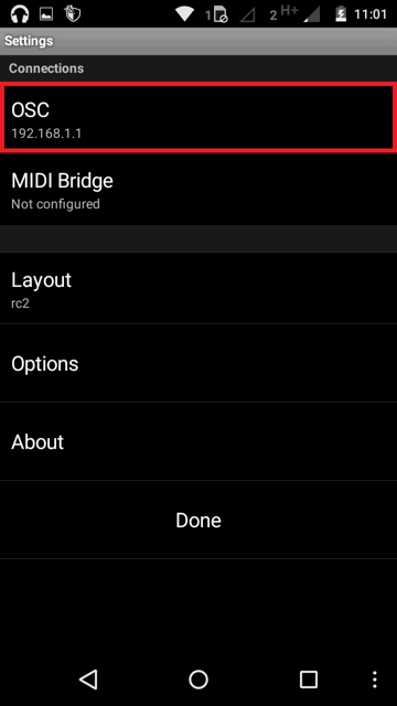
Tap on OSC submenu…
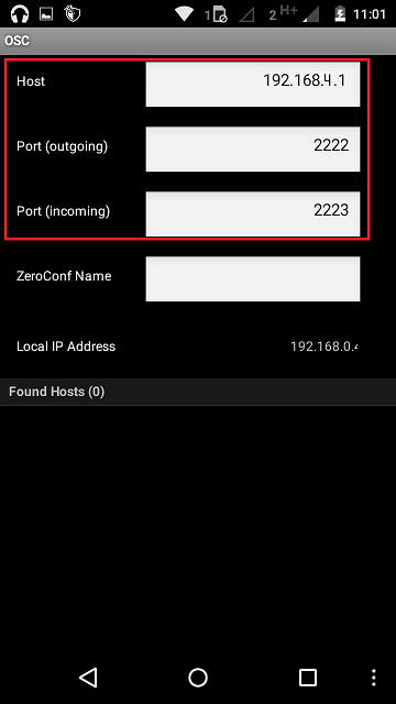
Populate the fields with these parameters
B-robot controls description (OSC touch layout):
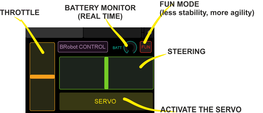
Above: Screen capture of layout you can use to control the B-robot if you choose the TOUCH-OSC control APP
LINK: OSCTouch layout used to control B-robot / github repository
Android users:
Because the Touch OSC app is not free, we have developed a FREE APP to control the Brobot (and future JJrobots) for your Android based Smartphone/Tablet:
It works in the same way the OSC touch app does: sending UDP packets to the B-robot. We have created a simple layout with Throttle and Steering slicers and two buttons. You can also use the Touch OSC app if you want to…
Steps to follow:
- Download and install the JJRobots control APP
- After turning the Brobot EVO ON, connect your smartphone/tablet to the B-robot EVO´s wifi network (remember, the WIFI´s password is 87654321)
- Launch the JJrobots control APP and play with your B-robot EVO!
B-robot controls description (JJrobots control APP):
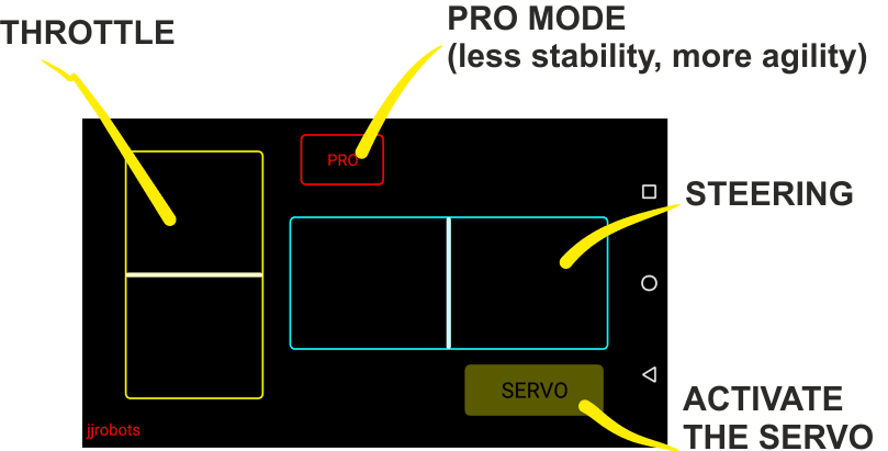
Above: Screen capture of the JJrobots B-robot control APP (available for free in GOOGLE PLAY)
controlling the B-ROBOT
TROUBLESHOOTING:
There is a DEBUG MODE inside the B-robot CODE. This MODE will allow you the debug the behaviour of the robot if you are having issues. Please, refer to the B-robot community if you have problems or questions.
Look at the sketch line “#define DEBUG 0″ and change the 0 to 1…8 depending on what info you want to get. Take a look to the CODE below:
#if DEBUG==8
Serial.print(throttle);
Serial.print(” “);
Serial.print(steering);
Serial.print(” “);
Serial.println(mode);
#endif
//angle_adjusted_radians = angle_adjusted*GRAD2RAD;
#if DEBUG==1
Serial.println(angle_adjusted);
#endif
//Serial.print(“\t”);
mpu.resetFIFO(); // We always reset FIFO
// We calculate the estimated robot speed:
// Estimated_Speed = angular_velocity_of_stepper_motors(combined) – angular_velocity_of_robot(angle measured by IMU)
actual_robot_speed_Old = actual_robot_speed;
actual_robot_speed = (speed_M1 + speed_M2)/2; // Positive: forward
int16_t angular_velocity = (angle_adjusted-angle_adjusted_Old)*90.0; // 90 is an empirical extracted factor to adjust for real units
int16_t estimated_speed = -actual_robot_speed_Old – angular_velocity; // We use robot_speed(t-1) or (t-2) to compensate the delay
estimated_speed_filtered = estimated_speed_filtered*0.95 + (float)estimated_speed*0.05;
#if DEBUG==2
Serial.print(” “);
Serial.println(estimated_speed_filtered);
#endif
// SPEED CONTROL: This is a PI controller.
// input:user throttle, variable: estimated robot speed, output: target robot angle to get the desired speed
//target_angle = (target_angle + speedPControl(estimated_speed_filtered,throttle,Kp_thr))/2.0; // Some filtering : Average with previous output
//target_angle = target_angle*0.3 + speedPIControl(dt,estimated_speed_filtered,throttle,Kp_thr,Ki_thr)*0.7; // Some filtering
target_angle = speedPIControl(dt,estimated_speed_filtered,throttle,Kp_thr,Ki_thr);
target_angle = constrain(target_angle,-max_target_angle,max_target_angle); // limited output
#if DEBUG==3
Serial.print(” “);
Serial.println(estimated_speed_filtered);
Serial.print(” “);
Serial.println(target_angle);
#endif
#if DEBUG==10
Serial.print(angle_adjusted);
Serial.print(” “);
Serial.println(debugVariable);
#endif
#if DEBUG==6 //BATTERY STATUS
Serial.print(“B”);
Serial.println(battery);
Serial.print(” “);
#endif
#if DEBUG==7
Serial.print(distance_sensor);
Serial.print(” A”);
Serial.println(autonomous_mode_status);
USEFUL INFO: ARDUINO LEONARDO, IMU 6050 & STEPPER MOTOR DRIVER(A4988):
Arduino Leonardo:
MPU-6050 (gyro+accelerometers)
- MPU-6050 series info can be found here
- How to integrate it with any Arduino, here
- Schematic and connection info, here
Stepper motor driver A4988:
FAQ (frequently asked questions):
Why are you using Stepper motors?
There are several options for motors: DC, Brushless, Steppers… We choose stepper motors because they have enough torque, you could connect the wheels directly without gears that generate some backslash (this is a common problem in balancing robots), they have good bearings and you will be able to control the speed of the motors with accuracy. In standard sizes these motors are cheap (we use the same motors used on a regular 3D printers) and the drivers are cheap and easy to interface with Arduino too.
Why you use a Wifi connection?
Using a Wifi connection allow us to work with a lot of devices (Smartphones, Tablets, PCs…) Bluetooth devices are cheaper but their range is usually shorter. Old devices are not supported and you could not connect it to Internet easily. The Wifi module that we recommend, allow us to create an Access Point, so you don’t need to use an existing Wifi infrastructure (cheap Wifi modules don´t let you do this). You can connect your device directly to the Robot anywhere but if you prefer you can hack it and use your own infrastructure therefore controlling your robot (or whatever you have created) over the Internet from any remote place in the world! (Cool, isn´t it?)
Why BROBOT?
Self balancing robots are fun to see and play. A self balancing robot requires sensors and control algorithms. You will find all the HOWTO and technical documents which explains the “behind the scenes” in JJROBOTS. Learn electronics and robotics creating your own BROBOT from scratch!.
There are some commercial solutions to the balancing robot, but here we want to share knowledge and thoughts. You can use the BROBOT parts to create more robots or gadgets, keep in mind all the devices used in a BROBOT are standard devices/electronics with a lot of potential. In the JJROBOTS community we want to show you how! You are now buying a self balancing robot, your are buying your own electronic and ancillary devices!
Thinking about creating a GPS self guidance robot? a modified version of BROBOT is your robot!
How much payload could carry BROBOT?
BROBOT could easily carry your soft-drink cans. We have tested with 500g of payload with success. More weight makes the robot more unstable but this could be fun also, isn’t it?
Why use stepper motors for a balancing robot?
There are several options for motors, DC, Brushless, Steppers… We choose stepper motors because they have enough torque, you could connect the wheels directly without gears that generate some backslash, they have good bearings and you could control the speed of the motors very precisely. Also they are cheap and the drivers too…
Could I use rechargeable batteries of Lipo batteries?
Yes, you could use standard AA batteries (alkaline recommended), AA rechargeable batteries (e.g. NiMh) or you could optionally use a 3S Lipo battery. If you use a Lipo battery we recommend you to enable the battery monitor and automatic shutoff (see Brobot documentation) You should recharge the batteries with your own charger. Run Lipo batteries at your own responsibility.
What is the runtime of BROBOT?
With rechargeable AA batteries (e.g. Ni-Mh 2100mAh) you could expect around half to an hour of runtime
Could BROBOT work without the wifi module?
Yes, BROBOT could work and keep its stability. But, of course you could not control it without the wifi module.
What APP do you recommend to control BROBOT?
We recommend TouchOSC app (you have to buy it but it´s cheap!) that is available for IOS and Android (Smartphone and tablets). You could download at JJROBOTS a template with controls adapted to BROBOT. You could also define your own layout if you want (PC layout editor). Cool app!
Why use OSC protocol for communications?
OSC (Open Sound Control) is an open protocol based on UDP messages to control music instruments. The main advantage is that is an open protocol with available apps for IOS, Android, PC… that let you customize your controls.
BROBOT understand some OSC messages (fader, push, toggle messages) that let you control it.
Could I change the name of the Wifi network that BROBOT generate?
Yes, on the configuration sketch you could change the name and also some other internet configurations. You could also connect BROBOT with your existing Wifi network (see configuration examples).
Is this a project for an Arduino beginner?
Well, BROBOT is not an easy beginner project, but it has a lot of documentation so you have a platform to grow your skills. You could first mount your BROBOT following the instructions and it should work OK, then you could start understanding some parts of the code and finally writing your own pieces of code…
For example it could be easily (there are tutorials for this) to write your code so the robot automatically move the arm and spin itself if you don’t send a command in 10 seconds…
More advanced hacks: Convert to a totally autonomous robot with obstacle avoiding adding a SONAR, convert to a follow line robot, and so on…
Why BROBOT electronics are not so cheap?
We are a really small startup (2 persons on our free time) and now we could only run small batch of electronics. As yo know the price of electronics drops quickly in high volume productions but we are starting… If we sell many boards and we could run more volume productions we will drop the prices!!. JJROBOTS didn´t born to get money, our spirit is to sell “good products” to found our next projects and spread the robotics knowledge
Have fun!
If you have question, please go to the B-robot´s FORUM. The community will appreciate your thoughts and ideas.