An LED resistance calculator is perfect for when you have a single LED and need to know which resistor you should use.
Outputs

Overview
Every light emitting diode (LED) has a current that they can safely handle. Going beyond that maximum current, even briefly, will damage the LED. Thus, limiting the current through the LED with the use of a series resistor is a common and simple practice. Note that this method is not recommended for high current LEDs, which need a more reliable switching current regulator.
This calculator will help you determine the value of the resistor to add in series with the LED to limit the current. Just input the indicated values and press the "Calculate" button. As a bonus, it will also calculate the power consumed by the LED.
Equation
$$R = \frac{V_{s}-V_{led}*X}{I_{led}}$$
Where:
$$V_{s}$$ = Supply voltage
$$I_{led}$$ = LED current. The usual operating range of common 3 mm and 5 mm LEDs is 10-30 milliamps. If access to an LED's datasheet is impossible, 20 mA is a good guess.
$$V_{led}$$ = LED voltage drop. The voltage drop on a LED depends on the color it emits. Here is a neat table of each color and their corresponding voltage drop:
$$X$$ = number of LEDs in series
| Color | Voltage Drop (V) |
| red | 2 |
| green | 2.1 |
| blue | 3.6 |
| white | 3.6 |
| yellow | 2.1 |
| orange | 2.2 |
| amber | 2.1 |
| infrared | 1.7 |
| other | 2 |
Bonus: Identifying LED Terminals
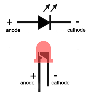
An LED has a positive (anode) lead and a negative (cathode) lead. The schematic symbol of the LED is similar to the diode (as shown above) except for two arrows pointing outwards. The anode (+) is marked with a triangle and the cathode (-) is marked with a line.
The longer lead of an LED is almost always the positive (anode) lead, while the shorter one is the negative (cathode). Also, if you look inside the LED, the smaller of the metal pieces is connected to the anode while the bigger one is connected to the cathode (see diagram above).